
Horizontal steel coil clamp

A technology of clamps and horizontal coils, which is applied in the direction of load hanging components, safety devices, transportation and packaging, etc. It can solve problems such as abnormal crimping quality, excessive contraction of clamp arms, and pinch damage on the end surface of steel coils. The effects of pinching and scratching, improving safety performance, and preventing coil hanging

Active Publication Date: 2015-07-22
SHANDONG IRON & STEEL CO LTD
View PDF7 Cites 9 Cited by
  • Summary
  • Abstract
  • Description
  • Claims
  • Application Information

AI Technical Summary

Problems solved by technology

[0002] Lifting equipment is needed in the production of steel plates and strips to transfer the produced steel coils from one process to another. Due to the different width of the steel coils or the abnormal quality of the coils, there is no Position detection often leads to pinching or scratching accidents on the end face of the steel coil. Through on-site observation, it is found that the real reason for pinching the steel coil is that the torque motor cannot accurately detect every clamping action, and the control clamp arm The clamping force with the end face of the steel coil will cause the clamp arm to shrink too tightly, resulting in hard contact friction between the clamp arm and the end face of the steel coil, resulting in damage to the end face of the steel coil. Insufficiency will easily lead to the following two situations. One is that the strip is pinched due to uneven coiling (overflow edge ≤ 20mm), and the other is that the end surface of the steel coil is scratched due to the inadequacy of the clamp, resulting in defective steel coils.

Method used


Image

  • Horizontal steel coil clamp

Examples


Embodiment Construction

[0016] The present invention will be further described below in conjunction with accompanying drawing of description and specific embodiment:

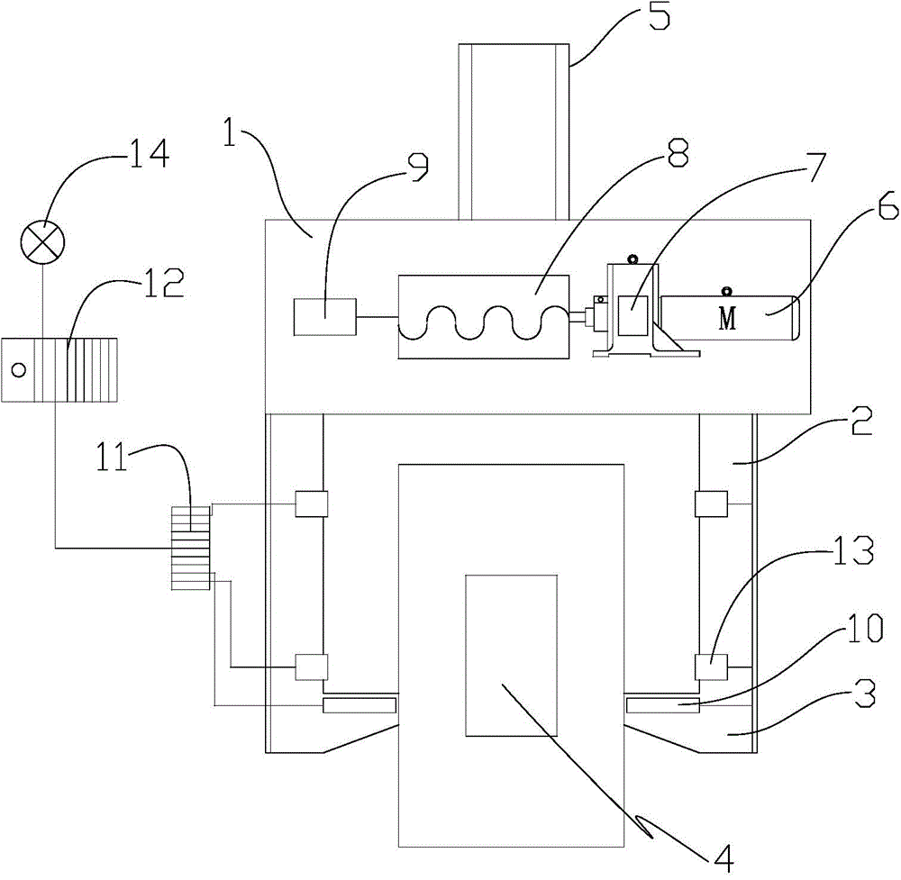
[0017] Such as figure 1 shown. A horizontal rolling clamp of the present invention includes a beam 1, a hanger 5, a clamp arm 2 and a hook 3,

[0018] Described hanger 5 is arranged on the top of crossbeam 1, clamping arm 2 comprises two, two clamping arms 2 are arranged below crossbeam 1, hook 3 is arranged on the bottom end of crossbeam 1, and two hooks 3 are arranged symmetrically;

[0019] The beam 1 is provided with a drive motor 6, the output shaft of the drive motor 6 is connected to the input end of the reducer 7, the output end of the reducer 7 is connected to the power input end of the gear transmission system 8, and the power output end of the gear transmission system 8 Connect the clamp arm 2;

[0020] The hook 3 is provided with a photoelectric switch 10, and the photoelectric switch 10 is connected to the PLC controlle...


PUM


Abstract

The invention discloses a horizontal steel coil clamp. The horizontal steel coil clamp is characterized by comprising a beam, a hanging bracket, a clamping arm and a pothook, wherein a driving motor, a reduction gear, a gear transmission system and a lubrication system are arranged in the beam; a photoelectric switch is arranged on the pothook and connected to a PLC controller through an intermediate terminal strip; a steel coil detector is arranged on the clamping arm and comprises a range sensor and an indicator lamp. The steel coil detector can monitor closing of the clamp in real time, ensures in-time monitoring of the steel coil position in the coil fetching process, ensures the safe clamping situation of the steel coil, and avoids the problem that the steel coil end surface is damaged by clamping and scratched due to over shrinkage of the clamp, so as to reduce quality loss; the horizontal steel coil clamp can effectively control the clearance between the hoisted steel coil and the clamp, reduces the influence of the manual operating skill factor on the hoisting quality, increases the automation control level of the clamp in the steel coil clamping and hoisting process, and is safe and reliable.

Description

technical field [0001] The invention relates to hoisting of steel coils in the field of steel rolling, in particular to a horizontal coil clamp. Background technique [0002] Lifting equipment is needed in the production of steel plates and strips to transfer the produced steel coils from one process to another. Due to the different width of the steel coils or the abnormal quality of the coils, there is no Position detection often leads to pinching or scratching accidents on the end face of the steel coil. Through on-site observation, it is found that the real reason for pinching the steel coil is that the torque motor cannot accurately detect every clamping action, and the control clamp arm The clamping force with the end face of the steel coil will cause the clamp arm to shrink too tightly, resulting in hard contact friction between the clamp arm and the end face of the steel coil, resulting in damage to the end face of the steel coil. Insufficiency will easily lead to th...

Claims


Application Information

Patent Timeline
IPC IPC(8): B66C1/42B66C13/48B66C13/46B66C15/06F16H57/04
CPCB66C1/42B66C13/46B66C13/48B66C15/06F16H57/04
Inventor 程龙李群姜起闻青山李广阔刘丽胡国雄刘爱民
Owner SHANDONG IRON & STEEL CO LTD
Learn More