Impeller type wet spraying machinery

A technology of wet spraying machine and impeller type, which is applied in the direction of shaft lining, tunnel lining, underground chamber, etc., can solve the problems of increasing the difficulty and manufacturing cost of the rotor, the structure of the spraying machine is not compact, and the reduction of work efficiency, etc., to achieve The effect of reducing feeding time and spraying interval time, ingenious air intake mode, reducing processing difficulty and manufacturing cost

Active Publication Date: 2015-07-22
河南省耿力工程设备有限公司
View PDF6 Cites 4 Cited by
  • Summary
  • Abstract
  • Description
  • Claims
  • Application Information

AI Technical Summary

Problems solved by technology

Arc grooves also increase the processing difficulty and manufacturing cost of the rotor
The air inlet and outlet are set on the outer side of the upper stator, so that the structure of the shotcrete machine is not compact
At the same time, the spraying machine does not have an automatic feeding mechanism, which increases the labor intensity and reduces the work efficiency.

Method used


Image

  • Impeller type wet spraying machinery
  • Impeller type wet spraying machinery
  • Impeller type wet spraying machinery

Examples


Embodiment Construction

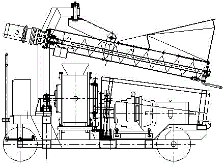
[0031] Such as figure 1 Shown, the impeller type wet spraying machine of the present invention comprises feeding device, hopper, feeding host, power unit and frame.

[0032] Wherein, the upper part of the feeding device is located above the feeding main machine, and the feeding device is arranged obliquely. The feed port corresponds to the position of the blanking port. The feeding host is installed on the frame and driven by the power unit.

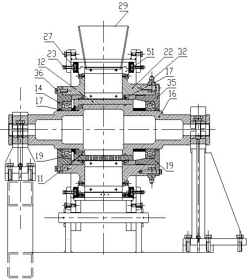
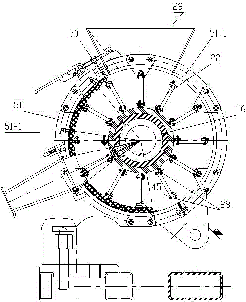
[0033] Such as figure 2 , 3 As shown, the feeding host includes a horizontally arranged rotor 22, a stator ring 51, and a hollow intermediate shaft 16. The hollow intermediate shaft 16, the rotor 22, and the stator ring 51 are coaxially arranged, and the rotor 22 is located between the hollow intermediate shaft 16 and the stator ring 51. , along the circumferential direction of the rotor 22, material cavities are arranged at intervals, the material cavities are separated by partitions arranged on the rotor 22, and the material cavit...


PUM


Abstract

The invention provides impeller type wet spraying machinery which comprises a material supply device, a material feeding main machine, a power device and a rack. Both the material feeding main machine and the power device are arranged on the rack. The power device is connected with the material feeding main machine in a drive mode. The material feeding main machine comprises a transverse stator ring, a rotor and a hollow middle shaft. The stator ring, the rotor and the hollow middle shaft are coaxially arranged. Sealing structures are arranged between the two sides of the stator ring and the rotor, sealing structures are arranged between the two sides of the rotor and the hollow middle shaft, and the rotor is located between the hollow middle shaft and the stator ring. The rotor is provided with material cavities at intervals in the peripheral direction of the rotor, and the material cavities are through holes. The stator ring comprises two arc-shaped ring bodies. The two arc-shaped ring bodies form a whole circle. The ends of the two arc-shaped ring bodies are connected, and the other ends of the two arc-shaped rings are connected through a locking device. The upper portion of the stator ring is provided with a feeding opening, and the bottom of the stator ring is provided with a discharging opening. According to the impeller type wet spraying machinery, compared with a vertical pulp shooting machine, the feeding time and the pulp spraying interval time are reduced, working efficiency is improved, the structure is more compact compared with a horizontal pulp shooting machine, the air inlet mode is more ingenious, and the rotor machining difficulty and the manufacturing cost are lowered.

Description

technical field [0001] The invention relates to the field of wet spraying machines, in particular to an impeller type wet spraying machine. Background technique [0002] Existing wet concrete spraying machine mainly can be divided into vertical spraying machine and horizontal spraying machine structurally. [0003] In the vertical spraying machine, the two ends of the rotor are provided with vertical through holes along the axial direction as the material cavity, and the upper and lower openings of the rotor material cavity are sealed by the upper and lower sealing plates. The upper sealing plate is provided with a material inlet corresponding to the upper opening of the rotor material chamber, the upper part of the material inlet is corresponding to the lower material opening of the hopper, and the lower sealing plate is provided with a material outlet corresponding to the caliber of the round tube of the material chamber. The discharge port is connected with a discharge ...

Claims


Application Information

Patent Timeline
Patent Type & Authority Applications(China)
IPC IPC(8): E21D11/10E04G21/04E02D15/02
Inventor 周永力李卫平孙伟
Owner 河南省耿力工程设备有限公司
Why Eureka
Try Eureka