
Gas turbine blade with longitudinal crossed rib cooling structure

A technology of cooling structure and gas turbine, which is applied to the supporting elements of blades, machines/engines, mechanical equipment, etc., can solve the problem of weakening the heat exchange effect between the cooling airflow and the blade body, enhancing the life loss of turbine blades, and the utilization rate of cooling gas. Low problems, to achieve the effect of good overall cooling performance, simple structure, and improved utilization

Inactive Publication Date: 2015-07-22
HUANENG POWER INT INC +1
View PDF7 Cites 19 Cited by
  • Summary
  • Abstract
  • Description
  • Claims
  • Application Information

AI Technical Summary

Problems solved by technology

[0004] The cooling air flow flows in the channel, forming a thermal boundary layer with a certain thickness inside the rotary channel, which will weaken the heat exchange effect between the cooling air flow and the blade body, on the one hand, cause the temperature of the blade body to be too high, and enhance the life loss of the turbine blade; On the other hand, the utilization rate of the cooling gas is low, and the temperature of the cooling air flow flowing out from the trailing edge and the gas film hole is low, and it will be mixed with the high-temperature gas, which will cause a large mixing loss

Method used


Image

  • Gas turbine blade with longitudinal crossed rib cooling structure
  • Gas turbine blade with longitudinal crossed rib cooling structure
  • Gas turbine blade with longitudinal crossed rib cooling structure

Examples


Embodiment Construction

[0027] Below in conjunction with accompanying drawing, the present invention is described in further detail:

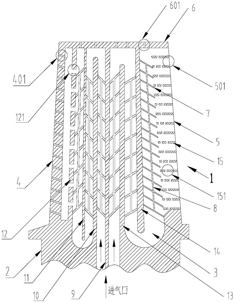
[0028] Such as figure 1 As shown, the present invention has a gas turbine blade with a longitudinally intersecting rib cooling structure, including an integrally formed airfoil 1 and a blade root platform 2, and a cooling chamber 3 is provided inside the airfoil 1, and the cooling chamber 3 is composed of The pressure surface and the suction surface of the airfoil 1, as well as the leading edge 4 and the trailing edge 5 are surrounded by a number of leading edge film cooling holes 401 on the leading edge 4, and a number of trailing edge holes 401 on the trailing edge 5. The air outlet hole 501, the top of the blade body 1 is provided with a top plate 6, the top plate 6 is provided with a number of blade top air film cooling holes 601, and the center of the blade root platform 2 is provided with an air inlet connected to it;

[0029] The inner surface of the pressure ...


PUM


Abstract

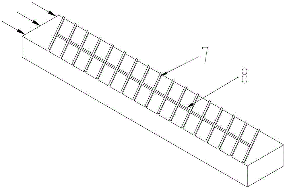
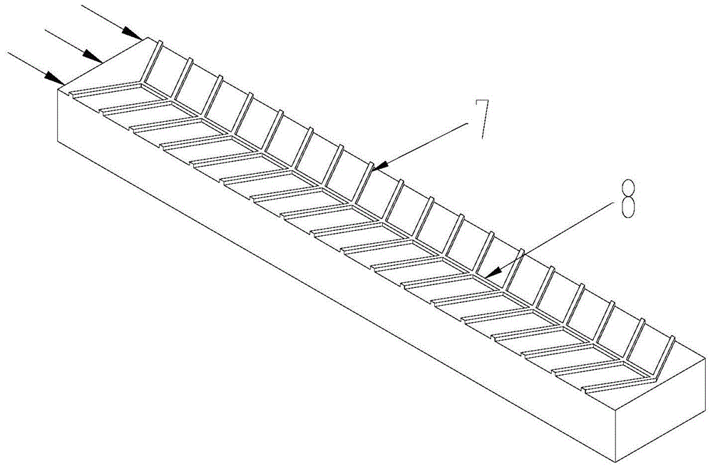
The invention discloses a gas turbine blade with a longitudinal crossed rib cooling structure. The gas turbine blade comprises a blade body, a blade root platform, an internal cooling chamber, forced-convection heat transfer fins, blade top air film cooling holes and the like. The longitudinal crossed rib cooling structure comprises a plurality of turbulent flow ribs arranged on the surface of the inner wall of the blade at equal intervals, and a forced-convection heat transfer loop of longitudinal crossed fins crossed with the turbulent flow ribs, and at least one longitudinal crossed fin is arranged in the transverse direction of the forced-convection heat transfer loop. According to the gas turbine blade, the cooling structure of the turbulent flow ribs arranged at equal intervals and the longitudinal crossed fins crossed with the turbulent flow ribs is adopted, the internal vortex system structure of a cooling channel is changed, the heat transfer coefficient of the blade body is increased, the heat transfer characteristics of the turbine cooling blade is improved, and the service life of the blade is prolonged.

Description

Technical field: [0001] The invention relates to a gas turbine, in particular to a gas turbine blade with a longitudinal intersecting rib cooling structure. Background technique: [0002] With the continuous improvement of efficiency and output power requirements of modern gas turbines, the inlet temperature of the turbine also increases, which will greatly increase the heat load of turbine components. The development of new efficient cooling structures is related to the performance of gas turbines and even the entire gas turbine. [0003] At present, the leading edge of the cooling structure of the turbine adopts impingement-air film cooling, the design of high-performance ribs on the blade body and the design of spoiler column ribs on the trailing edge of the blade. The rotary channel cooling structure of the airfoil occupies an extremely important position in today's turbine cooling methods, and is a typical high-efficiency forced convection heat transfer technology. The...

Claims


Application Information

Patent Timeline
Patent Type & Authority Applications(China)
IPC IPC(8): F01D5/18F01D5/30
Inventor 于飞龙肖俊峰李园园段静瑶高松上官博南晴
Owner HUANENG POWER INT INC
Learn More