Eureka AIR delivers breakthrough ideas for toughest innovation challenges, trusted by R&D personnel around the world.

Fuel gas thermal power plant gland seal and vacuum system and start-stop control method thereof

A technology for vacuum systems and thermal power plants, applied in the directions of preventing leakage, engine components, machines/engines, etc., which can solve the problems of reduced thermal efficiency of steam turbines, uneven cooling and heating of steam turbine shafts, and inability to improve thermal efficiency of power plant thermal systems.

Active Publication Date: 2015-07-22
NORTH CHINA ELECTRICAL POWER RES INST +1
View PDF5 Cites 3 Cited by
  • Summary
  • Abstract
  • Description
  • Claims
  • Application Information

AI Technical Summary

Problems solved by technology

[0002] In the shaft seal and vacuum system of the existing gas-fired thermal power plant, the shaft seal system cannot well prevent the high-temperature and high-pressure steam in the steam turbine from leaking into the atmosphere, causing heat pollution, heat loss and safety problems, and cannot prevent the external cold air from entering the steam turbine. , causing the thermal efficiency of the steam turbine to decrease, or causing the shaft of the steam turbine to bend due to uneven heating and cooling
The vacuum system cannot make the high-temperature and high-pressure steam go through the steam turbine to reduce the temperature and pressure to form an enthalpy drop, which cannot improve the thermal efficiency of the thermal system of the power plant
In addition, the shaft seal and vacuum system of the existing gas thermal power plant cannot realize the automatic start of the shaft seal and vacuum system, and cannot realize the automatic stop of the shaft seal and vacuum system in the running state
It is impossible to realize the automatic start-up of the shaft seal and vacuum system in the state of partial start-up of the shaft seal and vacuum system of the gas-fired thermal power plant without disturbing the original operating state

Method used


Image

  • Fuel gas thermal power plant gland seal and vacuum system and start-stop control method thereof
  • Fuel gas thermal power plant gland seal and vacuum system and start-stop control method thereof
  • Fuel gas thermal power plant gland seal and vacuum system and start-stop control method thereof

Examples


Embodiment Construction

[0065] The following will clearly and completely describe the technical solutions in the embodiments of the present invention with reference to the accompanying drawings in the embodiments of the present invention. Obviously, the described embodiments are only some, not all, embodiments of the present invention. Based on the embodiments of the present invention, all other embodiments obtained by persons of ordinary skill in the art without making creative efforts belong to the protection scope of the present invention.

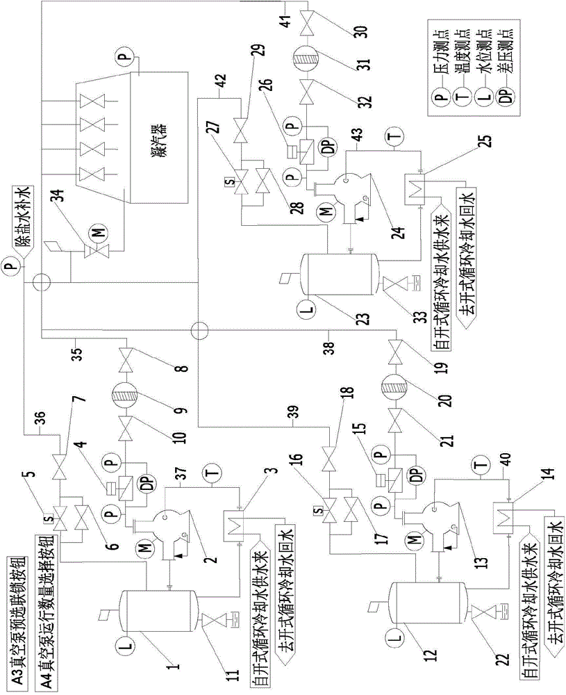
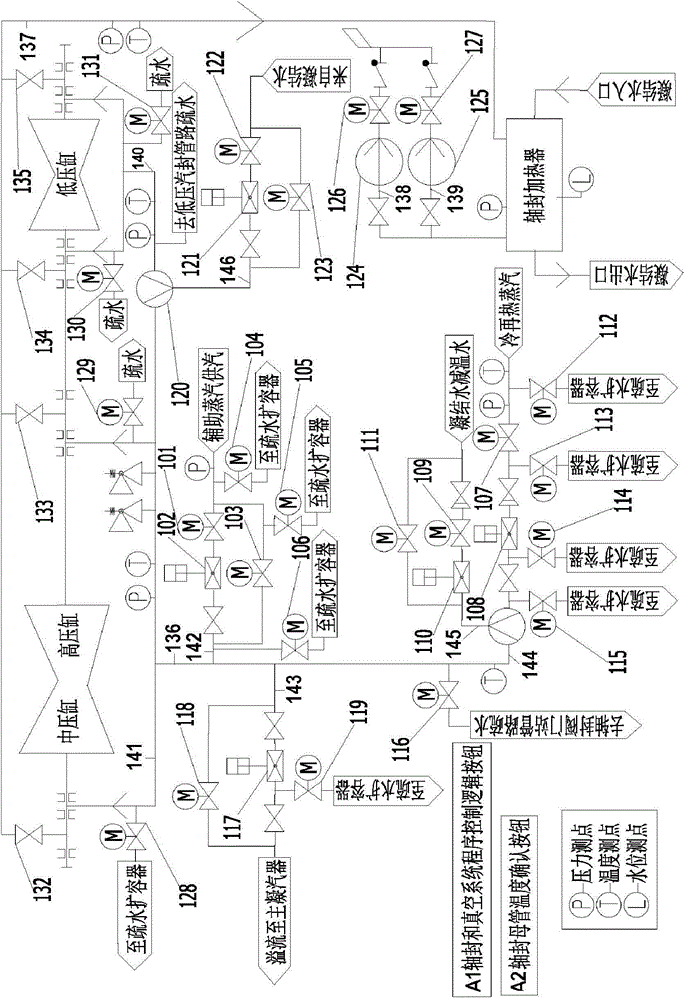
[0066] An embodiment of the present invention provides a shaft seal and vacuum system of a gas-fired thermal power plant. The shaft seal and vacuum system of a gas-fired thermal power plant includes: a vacuum system and a shaft seal system.

[0067] Such as figure 1 As shown, the vacuum system includes: a first vacuum pump system, a second vacuum pump system and a third vacuum pump system.

[0068] Among them, the first vacuum pump system includes: #1 steam-w...

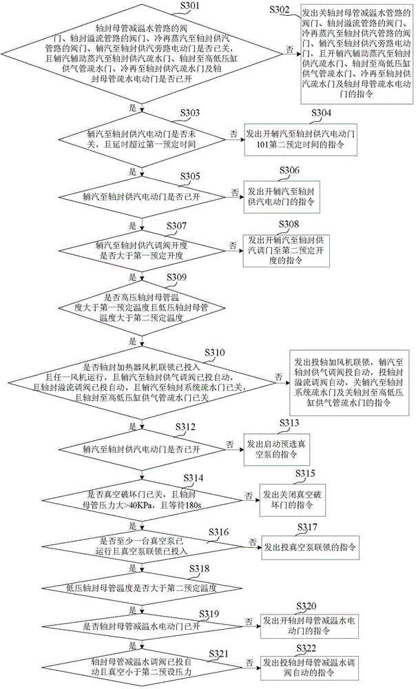

PUM


Abstract

The invention provides a fuel gas thermal power plant gland seal and vacuum system and a start-stop control method thereof. The fuel gas thermal power plant shaft seal and vacuum system comprises a vacuum system and a gland seal system; the vacuum system comprises a first vacuum pump system, a second vacuum pump system and a third vacuum pump system; each vacuum pump system comprises a steam separator, a water ring vacuum pump, a plate heat exchanger, a vacuum pumping pipeline, a water replenishing pipeline, a heat exchanging pipeline, a vacuum pump inlet pneumatic door, a vacuum pump water replenishing electromagnetic valve, a vacuum pump water replenishing bypass hand valve, a vacuum pump water replenishing main gate, a vacuum pump filter screen inlet hand gate, a vacuum pump inlet filter screen and a vacuum pump filter screen outlet hand gate. By means of the fuel gas thermal power plant gland seal and vacuum system and the start-stop control method thereof, the automatic start of the plant gland seal and vacuum system can be achieved, and the automatic stop of the plant gland seal and vacuum system is achieved in an operation state; under the state that the fuel gas thermal plant gland seal and vacuum system is partially started, the automatic start of the gland seal and vacuum system is achieved, and an original operation state is not interfered.

Description

technical field [0001] The invention relates to the technology of a gas-fired thermal power plant, in particular to a shaft seal and a vacuum system of a gas-fired thermal power plant and a start-stop control method thereof. Background technique [0002] In the shaft seal and vacuum system of the existing gas-fired thermal power plant, the shaft seal system cannot well prevent the high-temperature and high-pressure steam in the steam turbine from leaking into the atmosphere, causing heat pollution, heat loss and safety problems, and cannot prevent the external cold air from entering the steam turbine. , causing the thermal efficiency of the steam turbine to decrease, or causing the shaft of the steam turbine to bend due to uneven cooling and heating. The vacuum system cannot make the high-temperature and high-pressure steam go through the steam turbine to reduce the temperature and pressure to form an enthalpy drop, and cannot improve the thermal efficiency of the thermal sy...

Claims


Application Information

Patent Timeline
Patent Type & Authority Applications(China)
IPC IPC(8): F01D11/00F01D21/00
Inventor 任彦黄葆华司派友刘双白吕炜左川
Owner NORTH CHINA ELECTRICAL POWER RES INST
Why Eureka
Eureka Blog
Learn More