
Rotation type energy recovery device

An energy recovery device, a rotary technology, which is applied to fluid pressure actuation devices, engine seals, engine components, etc., can solve the problems of requiring a large rotational torque, difficulty in miniaturization of devices, and difficult practical commercial application value, etc. The effect of reducing operating noise, reducing rotational torque, and reducing drive power

Active Publication Date: 2015-07-22
丁武龙
View PDF8 Cites 10 Cited by
  • Summary
  • Abstract
  • Description
  • Claims
  • Application Information

AI Technical Summary

Problems solved by technology

The products of ERI Company in the United States adopt a gap seal structure on the surface of the distribution plate. It is difficult for the energy recovery device to maintain a high recovery efficiency when the processing capacity is small, and it is difficult to miniaturize the device; The impulsive force cannot make the rotor rotate stably; the above-mentioned pressure exchanger is difficult to form a product with a small rated flow rate and a large rated flow rate with practical commercial application value; the brittleness of its engineering ceramics also greatly reduces the safety and stability of the equipment.
[0005] Chinese patent 201010197604.1 discloses a work-exchanging energy recovery device. The rotation of the rotating part of the pressure exchanger is driven by a motor, and the rotating part is composed of a heavy and long pressure exchange tube. This rotating part has a large moment of inertia , is driven by a motor and rotates at a low speed, which requires a large rotational torque. At this time, it is difficult to maintain the efficient and stable operation of the energy recovery device, especially for medium-to-large and super-large rated flow products. It is also difficult to achieve practical commercial applications for this type of pressure exchanger value

Method used


Image

  • Rotation type energy recovery device
  • Rotation type energy recovery device
  • Rotation type energy recovery device

Examples


Embodiment Construction

[0032] Exemplary embodiments of the present invention are described below in conjunction with the accompanying drawings, which include various details of the embodiments of the present invention to facilitate understanding, and they should be regarded as exemplary only. Accordingly, those of ordinary skill in the art will recognize that various changes and modifications of the embodiments described herein can be made without departing from the scope and spirit of the invention. Also, descriptions of well-known functions and constructions are omitted in the following description for clarity and conciseness.

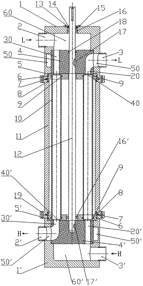
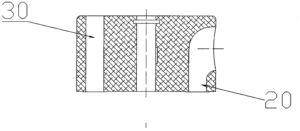
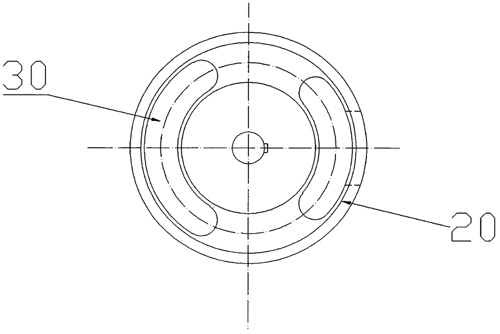
[0033] Refer to attached picture. It includes a rotating assembly, which includes: a drive shaft 12, a moving ring 15 for mechanical sealing sleeved outside the drive shaft, an upper flow distribution rotor 4, a lower flow distribution rotor 4', and the upper flow distribution rotor 4 is worn Insert the upper end of the drive shaft 12 and set a sealing ring 18 on the uppe...


PUM


Abstract

The invention provides a rotation type energy recovery device. The rotation type energy recovery device comprises a rotation assembly and a non-rotation assembly. The rotation assembly comprises a drive shaft, a movable ring, an upper flow distribution rotor and a lower flow distribution rotor, wherein the drive shaft is sleeved with the movable ring, and the movable ring is used for mechanical seal. The non-rotation assembly comprises a mechanical seal cover, a static ring, an upper end cover, an upper antifriction bearing, an upper thrust collar, a spring ring, a pressure exchange tube, a shell, a lower thrust collar, a lower antifriction bearing and a lower end cover, wherein the static ring is used for mechanical seal and is matched with the movable ring, the upper antifriction bearing is installed in the upper end cover, the pressure exchange tube is axially parallel to the drive shaft, and the lower antifriction bearing is installed in the lower thrust collar. The rotation type energy recovery device adopts motor drive, rotation flow distribution and self-tight seal, achieves efficient and stable pressure and energy exchange, solves the technical problem that a pressure exchanger in the prior art can not handle large or ultra-large flow, and meanwhile can replace a valve control power exchanger energy recovery device for large or ultra-large rated flow exchange processing and have stable and continuous flow and pressure.

Description

technical field [0001] The invention relates to a pressure energy recovery device in a liquid system. Background technique [0002] At present, in the work exchange type energy recovery device, the energy conversion process is pressure energy. It enables the high and low fluids to directly exchange pressure energy. If the friction and leakage in the device are ignored, the efficiency of the device can reach 100% in theory, but the actual efficiency can be more than 90%. It is this high recovery efficiency that makes it a hot spot of research and development by many researchers at home and abroad. According to the type of moving parts, such devices can be divided into two types: valve-controlled work exchanger (Worker Exchange) and pressure exchanger (Pressure Exchange). [0003] Valve-controlled work exchangers, representative products include Work Exchange Energy Recovery (DWEER) from Swiss Calder company, Presssure Exchange System (PES) from German Sigma company, DYPREX ...

Claims


Application Information

Patent Timeline
IPC IPC(8): F15B21/14F16J15/34
CPCF15B21/14F16J15/34
Inventor 丁武龙
Owner 丁武龙
Learn More