Housing for induction cooker or radiant cooker

A technology of electric ceramic cooker and induction cooker, applied in the direction of stove/stove base, etc., can solve the problems of poor structural strength, poor visual effect, poor oil stain resistance, etc., to improve aesthetics and coordination, highlight practical value, excellent Antibacterial and mildew proof effect

Inactive Publication Date: 2015-07-22
佛山市裕安金属制品有限公司
View PDF6 Cites 0 Cited by
  • Summary
  • Abstract
  • Description
  • Claims
  • Application Information

AI Technical Summary

Problems solved by technology

This kind of casing is not only complicated in structure and inconvenient for installation and maintenance; but also limited by the bending process of metal sheets, the shape is single and the structural strength is poor
However, the oil resistance of the plastic casing is poor, and it will be deformed after being heated, which will aggravate the aging of the plastic.
Some colors fade after a period of use, the visual effect is poor, and the service life is greatly restricted

Method used


Image

  • Housing for induction cooker or radiant cooker
  • Housing for induction cooker or radiant cooker
  • Housing for induction cooker or radiant cooker

Examples


Embodiment 1

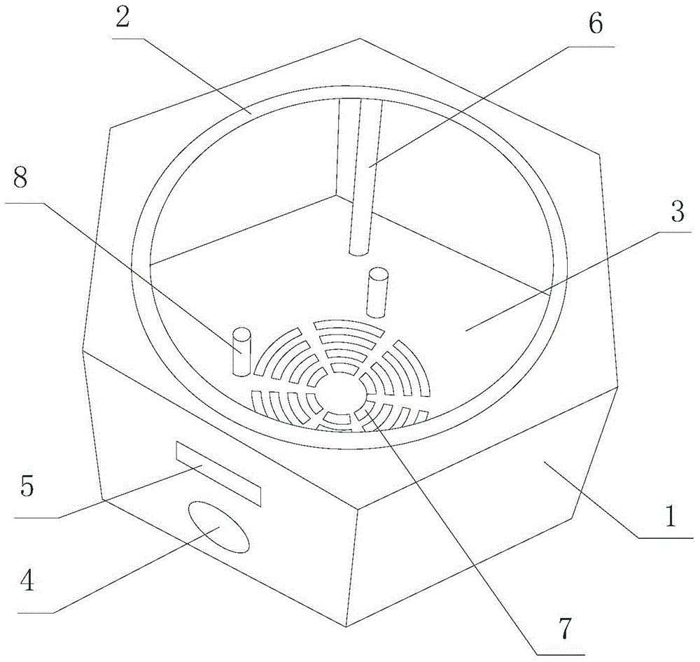
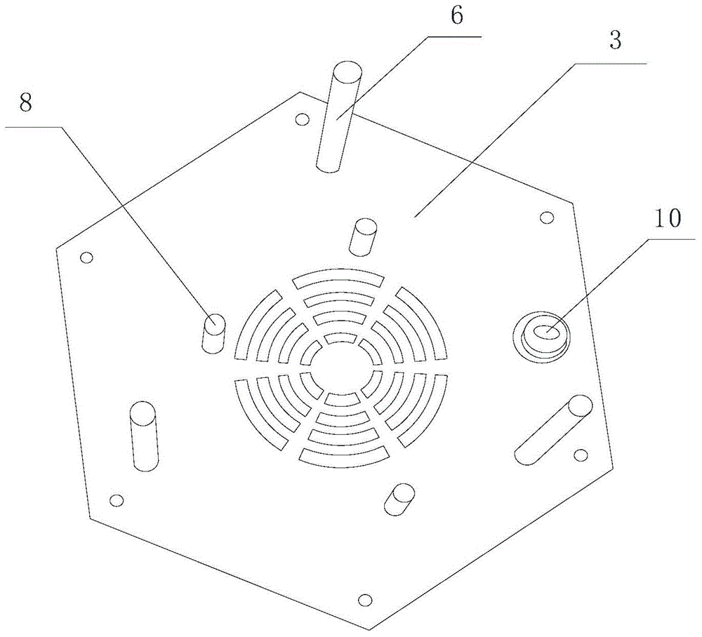
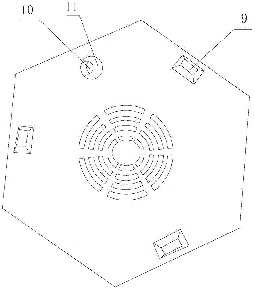
[0037] Such as figure 1 , figure 2 As shown, a shell frame for an electric ceramic stove includes: an integrally formed main body 1 , a panel mounting ring 2 formed on the upper part of the main body 1 , and a lower cover assembly 3 provided at the bottom of the main body 1 . Wherein, the main body 1 and the lower cover assembly 3 are formed by metal die-casting, and the surfaces of the main body 1, the panel mounting ring 2 and the lower cover assembly 3 are coated with a ceramic crystal layer whose color is consistent with that of the kitchen countertop.

[0038] In the present embodiment, the preferred ceramic crystal layer is made by spraying the ceramic crystal coating on the metal surface by spraying process; the ceramic crystal coating is an inorganic nano-scale coating, comprising by weight: aluminum silicate: 30 parts; nano-titanium dioxide : 10 parts; Pigment: 10 parts; Leveling agent: 1 part; Anti-settling agent: 1 part; Brightening agent: 1 part. Preferably, the...

Embodiment 2

[0042] A shell frame for an electric ceramic furnace provided in this embodiment is basically the same in structure as in Embodiment 1, the difference is that:

[0043] 1. The shape of the main body is a pentagonal prism, and the number of the support columns is five.

[0044] Two, the ceramic crystal coating comprises by weight:

[0045] Aluminum silicate: 70 parts;

[0046] Nano titanium dioxide: 40 parts;

[0047] Pigment: 40 parts;

[0048] Leveling agent: 5 parts;

[0049] Anti-sedimentation agent: 5 parts;

[0050] Brightening agent: 20 parts.

Embodiment 3

[0052] A shell frame for an electric ceramic furnace provided in this embodiment is basically the same in structure as in Embodiment 1, the difference is that:

[0053] 1. The shape of the main body is an octagonal prism, and the number of the supporting columns is eight.

[0054] Two, the ceramic crystal coating comprises by weight:

[0055] Aluminum silicate: 40 parts;

[0056] Nano titanium dioxide: 30 parts;

[0057] Pigment: 20 parts;

[0058] Leveling agent: 3 parts;

[0059] Anti-sedimentation agent: 3 parts;

[0060] Brightening agent: 10 parts.


PUM


Abstract

The invention discloses a housing for an induction cooker or a radiant cooker. The housing comprises an integrally formed main body, a panel mounting ring formed at the upper part of the main body, and a lower cover assembly arranged at the bottom of the main body; and both the main body and the lower cover assembly are made of metal, and surfaces of the main body, the panel mounting ring and the lower cover assembly are coated with ceramic crystal layers in color consistent with that of a kitchen table-board. Compared with the prior art, the integrally formed housing takes the place of a traditional curl formed metal housing or a die-cast formed plastic housing, and enables the integral color of the induction cooker or the radiant cooker to basically keep consistent with the color of the kitchen table-board, so that the aesthetic property and harmony of a kitchen are effectively improved. Experiments show that the housing provided by the invention not only is superior to similar materials in aspects of fire resistance and heat resistance, but also is superior to other metal housings in aspects of heat preservation and cleaning.

Description

technical field [0001] The invention relates to the technical field of household stoves, in particular to a shell frame for an electromagnetic stove or an electric ceramic stove. Background technique [0002] At present, electric ceramic stoves on the market generally include a casing, a heating core and a panel. The panel is arranged on the upper side of the heating plate. When working, the heat generated by the heating element of the heating core heats the panel, and the panel heats the placed items. . [0003] Existing electric ceramic stove casing mainly contains two kinds of metal and plastics. Wherein, the metal casing is formed by bending a metal plate to obtain an upper and lower opening structure, and upper and lower flanges are provided on the upper and lower ends of the main body of the casing, which are respectively used for arranging the upper cover assembly and the lower cover assembly. This casing is not only complicated in structure and inconvenient for ins...

Claims


Application Information

Patent Timeline
Patent Type & Authority Applications(China)
IPC IPC(8): F24C15/08
CPCF24C15/08
Inventor 杨志勇
Owner 佛山市裕安金属制品有限公司
Why Eureka
Try Eureka