Pollution source fine particulate matter dilution sampling method and device

A technology for fine particles and pollution sources, which is applied in the field of dilution sampling of fine particles of pollution sources, which can solve the problems of simultaneous collection, sampler volume, weight cost, increased energy consumption, labor and labor, etc.

Inactive Publication Date: 2015-07-22
QINGDAO JINGYIXIN ELECTRONICS TECH
View PDF8 Cites 6 Cited by
  • Summary
  • Abstract
  • Description
  • Claims
  • Application Information

AI Technical Summary

Problems solved by technology

In addition to increasing the size, weight, cost, and energy consumption of the sampler, PM cannot be calculated 2.5 Particulate Matter Concentration and Emissions
[0006] The existing samplers do not have real-tim

Method used


Image

  • Pollution source fine particulate matter dilution sampling method and device
  • Pollution source fine particulate matter dilution sampling method and device
  • Pollution source fine particulate matter dilution sampling method and device

Examples


Example Embodiment

[0034] Example 1

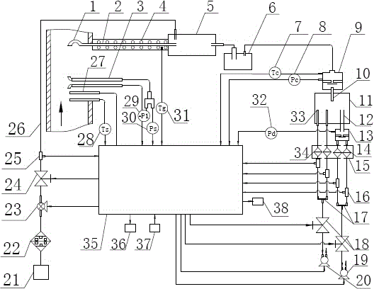
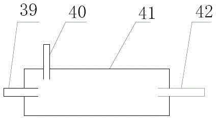
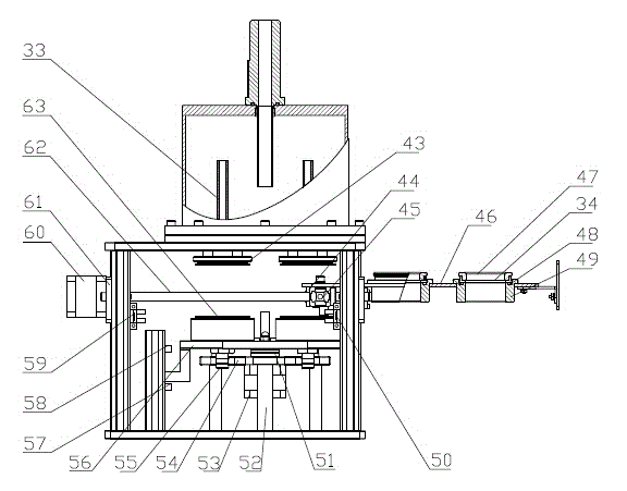
[0035] This embodiment is a pollution source four-channel PM 10 , PM 2.5 Synchronous sampling device, such as figure 1 , figure 2 , image 3 Shown. The device includes: sampling nozzle 1, sampling tube 2, pitot tube 3, heating device 4, diluter 5, retention chamber 6, temperature sensor Tc 7, pressure sensor P c 8. PM 10 Particle cutter 9, splitter 11, PM 2.5 Particle cutter 13, PM 2.5 Sampling filter membrane (m 3 , M 4 ) 14. Automatic film changing device 15, flow sensor q (q 1 , Q 2 , Q 3 , Q 4 ) 16, three-way pipe 17, solenoid valve (f 1 , F 2 ) 18. PM 2.5 Sampling pump 19, PM 10 Sampling pump 20, dilution gas pipeline 26, humidity sensor 27, pipeline temperature sensor T s 28. Pitot tube differential pressure sensor △P 1 29, pipeline pressure sensor Ps 30, temperature sensor T g 31. Pressure sensor P d 32, PM 10 Sampling filter membrane (m 1 , M 2 ) 34, single-chip microcomputer 35, display 36, keyboard 37, communication interface 38; the sampling no...

Example Embodiment

[0057] Example 2

[0058] The embodiment of the present invention is a six-channel PM 10 , PM 2.5 Synchronous sampling device, collect 3 PM at the same time 10 , PM 2.5 sample. In PM 10 After the particle cutter is connected in series with a splitter, 3 splitter outlet pipes are required to connect with 3 PM 10 Sampling filter membrane in series, PM 2.5 The air intake pipe of the particle cutter extends into the inside of the splitter, PM 2.5 Connect 3 PMs in series after the particle cutter 2.5 Sampling filter membrane, PM 10 Sampling filter and PM 2.5 The outlet of the sampling filter is respectively connected in series with the flow sensor q, the solenoid valve, and the sampling pump. The technical principle and measurement and control scheme are the same as those in Example 1.

[0059] The device of the present invention is also suitable for collecting other particle size particles, harmful gases, smoke, SVOCs samples and ambient air in the pipeline.

[0060] In summary, the pr...


PUM


Abstract

The invention relates to a pollution source fine particulate matter dilution sampling method and device. The device comprises a multifunctional sampling pipe, a retention chamber, a PM10 particulate matter cutter, a shunt, an automatic film changing device, a PM2.5 particulate matter cutter, a PM10 sampling filter film, a PM2.5 sampling filter film, a flow sensor q, a three-way pipe, an electromagnetic valve, a PM10 sampling pump, a PM2.5 sampling pump, a dilution gas channel system and pipeline, a single-chip microcomputer, a pitot pipe differential pressure sensor delta P1, a temperature sensor Tc, a pressure sensor Pc, a pressure sensor Pd, a display device, a keyboard and a communication interface, wherein the multifunctional sampling pipe, the retention chamber, the PM10 particulate matter cutter and the shunt are sequentially connected in series. The device provided by the invention can realize the functions of constant-speed sampling of sample gas, simultaneous constant-current graded sampling of particulate matters with different particle sizes in the sample gas, real-time measurement of humidity of the sample gas and automatic film changing, and also can figure out the emission concentration and emission amount of PM10 and PM2.5 according to the flow rate of the sample gas in the pipeline, the diameter of the pipeline, the sampling volume and the amount of PM10 and PM2.5 obtained by sampling.

Description

technical field [0001] The invention relates to a dilution sampling method and device for fine particles of pollution sources, belonging to the field of environmental protection monitoring instruments. Background technique [0002] The exhaust gas and fine particles discharged from the pollution source discharge pipeline (hereinafter referred to as the pipeline), because the humidity and temperature of the gas in the pipeline are higher than the ambient humidity and temperature, many dynamic physical and chemical dynamic processes (nucleation) will occur after being discharged into the ambient atmosphere. action, condensation, compression, etc.) and chemical processes that pollute the ambient air. In order to monitor the emission of fine particulate matter from pipelines and the source of air pollution, it is necessary to collect samples with a fine particulate matter sampler from the pollution source. [0003] Existing technologies are: [0004] The jet technology is used...

Claims


Application Information

Patent Timeline
IPC IPC(8): G01N1/24G01N1/38
Inventor 王丕征毛洪钧慎镛健邰珊珊赵焕宇张青新祖彪王帅杨文曲健董洪升于文柱李楠王清泉王敏王鹏
Owner QINGDAO JINGYIXIN ELECTRONICS TECH
Why Eureka
Try Eureka