Optical module assembly with inner heat dispassion channel and composite heat dispassion structure thereof

A technology of heat dissipation channel and heat dissipation structure, which is applied in the coupling of optical components, optical waveguides, light guides, etc., can solve the problem of large emission power and overall power consumption, no existing heat dissipation channels in the heat dissipation path, and can not meet the heat dissipation requirements of high-speed broadband optical modules, etc. problem, to achieve the effect of improving the heat dissipation efficiency and improving the heat dissipation effect

Inactive Publication Date: 2015-07-22
SOUTHEAST UNIV
View PDF9 Cites 20 Cited by
  • Summary
  • Abstract
  • Description
  • Claims
  • Application Information

AI Technical Summary

Problems solved by technology

[0004] A heat sink for an optical module in the prior art includes an optical module, a circuit board, and a heat sink. The natural heat dissipation is mainly performed by adding a heat sink above the module. The heat sink is fixed on the top of the module so that the optical module is in contact with the heat sink. Take the heat generated by the module, but with the implementation of 40G, 100G and even 400G optical networks, the working distance is 40km, and the 100GBASE-ER4 / 10 optical module with a power consumption level of more than 24W is still in the research and development stage, and its transmission power and overall power consumption Larger, the temperature requirements for optical modules are relatively more stringent, traditional heat dissipation solutions can no longer meet the heat dissipation requirements of high-speed broadband optical modules, affecting the normal operation of optical networks
[0005] For example, the Chinese invention patent application number is: CN102612302A, and the name of the invention is: optical module heat dissipation device and communication equipment. This patent adds a heat dissipation device to the optical module shell to improve the heat dissipation effect of its outer layer, but its internal heat dissipation path does not have a ready-made heat dissipation channel. , resulting in the inability to meet the heat dissipation effect

Method used


Image

  • Optical module assembly with inner heat dispassion channel and composite heat dispassion structure thereof
  • Optical module assembly with inner heat dispassion channel and composite heat dispassion structure thereof
  • Optical module assembly with inner heat dispassion channel and composite heat dispassion structure thereof

Examples


Embodiment Construction

[0026] The present invention will be further described below in conjunction with the accompanying drawings.

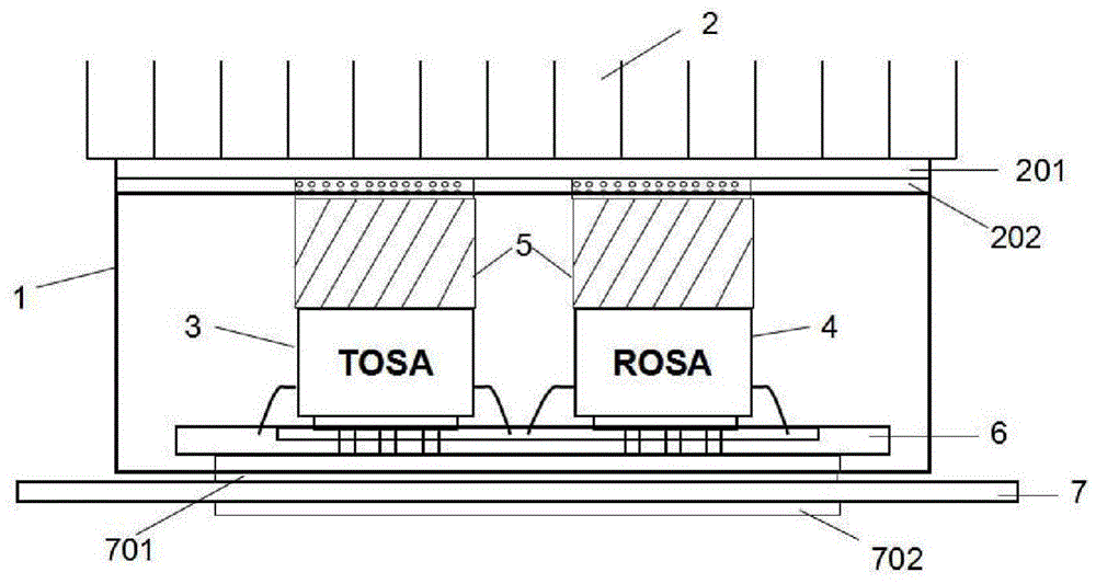
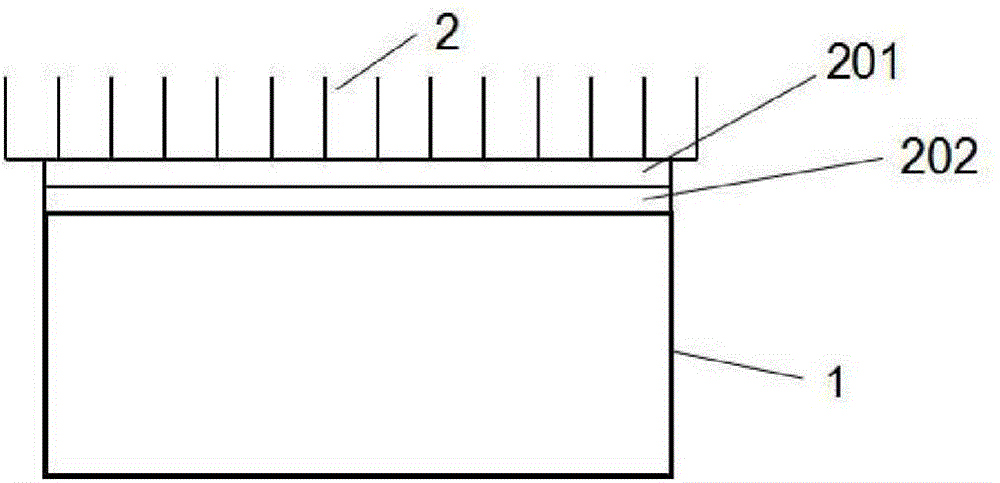
[0027] figure 1 As shown, heat conduction units are arranged between the internal components of the module, between the components and the module package shell, and between the module package shell and the external structural parts to form two upper and lower heat dissipation channels. The heat generated inside the module passes through the heat conduction unit from the inside Conduction to the top and bottom focuses on solving the heat dissipation problem between the internal components of the module. By adding a heat conduction unit inside the module, the heat generated by the heat source is quickly and evenly conducted upwards and downwards, thereby improving the overall cooling effect of the module.

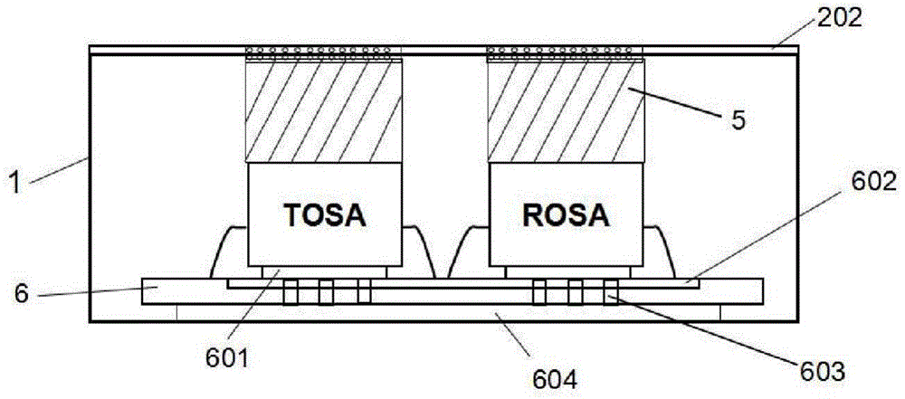
[0028] combine figure 1 and image 3 As shown, the composite heat dissipation structure includes an optical module packaging shell 1, a TOSA transmitting component...


PUM


Abstract

The invention discloses an optical module assembly with an inner heat dispassion channel and a composite heat dispassion structure thereof. The optical module assembly comprises an optical module packing housing, a cooling fin on the top of the module, a TOSA (transmitter optical subassembly), a ROSA (receiver optical subassembly) and an inner circuit board. The TOSA and the ROSA are fixedly arranged on the inner circuit board, a thermal pad is arranged on the top of the TOSA and the ROSA. The upper surface of the thermal pad is closely contacted with the optical module packing housing, and the lower surface of the optical module packing housing is connected with the outer big PCB board. By arranging two cooling channels up and down inside the optical module, a cooling path is increased and heat generated by the inner assembly can be quickly transmitted upward and downward to external environment through thermal conductive units. Compared with the prior art, the optical module assembly with the inner heat dispassion channel and composite heat dispassion structure has better cooling effect.

Description

technical field [0001] The invention relates to an optical module communication technology, in particular to an optical module component-level composite heat dissipation structure with internal heat dissipation channels at upper and lower ends. Background technique [0002] With the rapid development of data and network transmission, the information capacity of optical networks has increased sharply, and high-speed broadband optical modules have become a major research hotspot in the field of optical communication. Telecom operators are competing to deploy 100G and even 400G network construction, and the demand for optical router line cards and 40G / 100G optical modules has surged. High-speed optical modules are the core components to realize optical signal processing and form various miniaturized and highly integrated on-chip photonic systems and optical networks. The next-generation optical network architecture needs to meet the needs of ultra-large-capacity routing and sw...

Claims


Application Information

Patent Timeline
Patent Type & Authority Applications(China)
IPC IPC(8): G02B6/42
CPCG02B6/4269
Inventor 刘旭蔡媛媛孙小菡柏宁丰陈翰
Owner SOUTHEAST UNIV
Why Eureka
Try Eureka