Z-source three-level PWM (pulse width modulation) rectifier and method for controlling same

A control method and rectifier technology, which are used in electrical components, conversion devices for converting AC power input to DC power output, and output power, etc., can solve problems such as large harmonic content, and achieve good waveform quality, reduced distortion, and reliability. Sex-enhancing effects

Active Publication Date: 2015-07-22
SHANDONG UNIV
View PDF6 Cites 6 Cited by
  • Summary
  • Abstract
  • Description
  • Claims
  • Application Information

AI Technical Summary

Problems solved by technology

[0004] The disadvantage of the two-level PWM rectifier is that when it is applied to high-voltage and high-power occasions, it is necessary to use high back-voltage power switch tubes, or to use multiple power switch tubes in series
In addition, since the output voltage of the AC side of the rectifier with this structure is always switched between two levels, when the switching frequency is not high, the harmonic content will be relatively large

Method used


Image

  • Z-source three-level PWM (pulse width modulation) rectifier and method for controlling same
  • Z-source three-level PWM (pulse width modulation) rectifier and method for controlling same
  • Z-source three-level PWM (pulse width modulation) rectifier and method for controlling same

Examples


Embodiment Construction

[0061] The present invention will be further described below in conjunction with the accompanying drawings and embodiments.

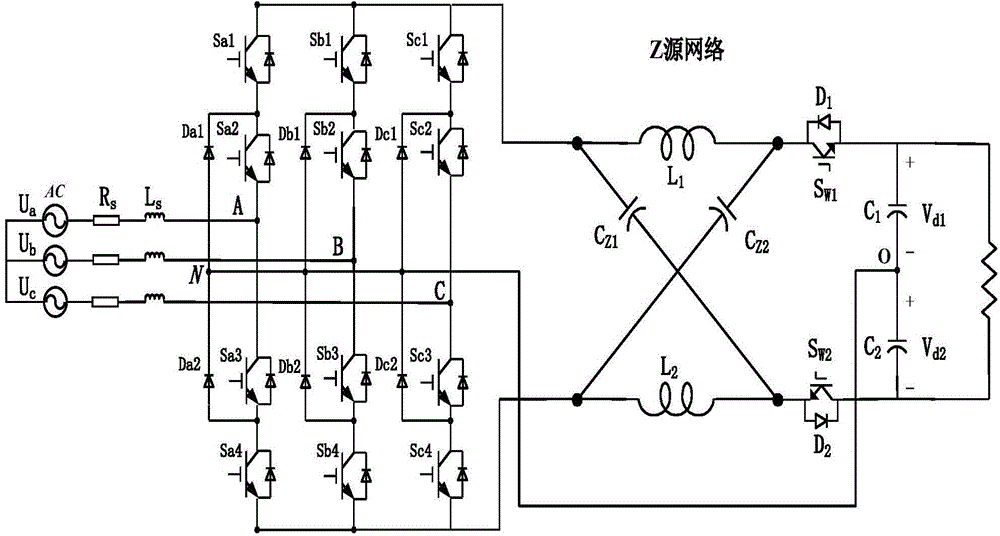
[0062] figure 1 In order to invent the structural diagram of the Z-source three-level rectifier, U a ,U b ,U c For an ideal voltage source: R S is the grid-side equivalent resistance, L S is the grid side inductance, C 1 and C 2 are DC side capacitors with equal capacitance (C 1 =C 2 ), and the corresponding voltages are V d1 and V d2 ,, o is the midpoint; the Z source network consists of two capacitors C connected into an X-like shape Z1 、C Z2 and two inductors L 1 and L 2 constitute. S W1 and S W2 are two switching tubes, respectively connected to two diodes D 1 and D 2 In anti-parallel, they are normally on in the non-shoot-through state and selectively turned off in a specific pass-through state.

[0063] The introduction of the Z source network makes it possible for each phase bridge arm of the rectifier to pass through. Therefo...


PUM


Abstract

The invention relates to a Z-source three-level PWM (pulse width modulation) rectifier and a method for controlling the same. The Z-source three-level PWM rectifier comprises three phases of bridge arms which are connected with one another in parallel. Each phase of bridge arm comprises four switch tubes which are serially connected with one another, and middle points of the various phases of bridge arms are connected with power grids or alternating-current sources by inductors to be used as input sources of the rectifier; output ends of the various bridge arms which are connected with one another in parallel are connected with an input end of a Z-source network; the switch tubes S<W1> and S<W2> are respectively serially connected to the upper side and the lower side of an output end of the Z-source network; a rear output end of the Z-source network is connected with a serial connection branch of a capacitor C1 and a capacitor C2 in parallel, and the serial connection branch of the capacitor C1 and the capacitor C2 is connected with a direct-current load. The Z-source three-level PWM rectifier and the method have the advantages that reduced voltages can be outputted by the Z-source three-level PWM rectifier with the topology, the upper and lower bridge arms can be directly connected with one another, the reliability can be obviously improved, dead time can be eliminated, and waveform distortion can be prevented; alternating-current harmonic voltages and currents can be effectively reduced by the Z-source three-level PWM rectifier while withstand voltage level can be upgraded, the quality of network-side waveforms of the Z-source three-level PWM rectifier can be improved in identical switch frequency and control modes, and distortion can be decreased.

Description

technical field [0001] The invention relates to a Z source three-level PWM rectifier and a control method thereof. Background technique [0002] Compared with the traditional uncontrolled rectification and phase-controlled rectification, the PWM rectifier realizes the sine of the grid-side current and can operate at unity power factor, so it has the advantages of high power factor, small output voltage ripple, and good dynamic response. PWM rectifiers are divided into voltage type rectifiers (VSR) and current type rectifiers (CSR). Among them, voltage type rectifiers have the advantages of bidirectional transmission of electric energy, power factor correction, and reduction of input harmonics, etc., and are widely used. Although the current source rectifier has the advantages of circuit protection and fast current response, its application is limited by the huge size of its AC side capacitance and DC side inductance. Ordinary voltage-type rectifiers only have the function o...

Claims


Application Information

Patent Timeline
IPC IPC(8): H02M7/219H02M1/14H02M1/44
CPCH02M7/487H02M7/219H02M1/126
Inventor 张承慧石秀岩陈阿莲邢相洋
Owner SHANDONG UNIV
Why Eureka
Try Eureka