Resonant cavity for verifying wood microwave pretreatment temperature distribution

A temperature distribution and resonant cavity technology, applied in microwave heating, heating devices, dryers, etc., can solve the problems of high wood cracking rate, unimprovable temperature distribution, unsatisfactory temperature distribution uniformity, etc., and achieve low wood cracking rate , Good uniformity of temperature distribution, microwave can evenly disperse the effect

Inactive Publication Date: 2015-07-22
CENTRAL SOUTH UNIVERSITY OF FORESTRY AND TECHNOLOGY
View PDF4 Cites 14 Cited by
  • Summary
  • Abstract
  • Description
  • Claims
  • Application Information

AI Technical Summary

Problems solved by technology

Although the microwave of the traveling wave heater can be absorbed by the wood through multiple reflections, the temperature distribution on the cross-section of the wood cannot be improved
Because the microwave energy of the traveling wave heater is relatively concentrated at the feed port, the local high temperature produces a wood cracking rate
Although the microwave energy utilization rate of the traveling wave heater is high, the temperature distribution uniformity is not ideal and the wood cracking rate is high, so it is not the best choice

Method used


Image

  • Resonant cavity for verifying wood microwave pretreatment temperature distribution
  • Resonant cavity for verifying wood microwave pretreatment temperature distribution
  • Resonant cavity for verifying wood microwave pretreatment temperature distribution

Examples


Embodiment 1

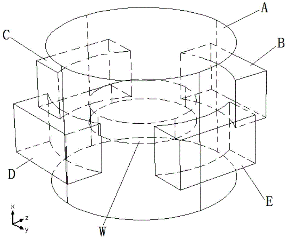
[0029] like figure 1 As shown, the resonant cavity used in this embodiment to verify the temperature distribution of wood microwave pretreatment includes a horizontally arranged main resonant cavity A, and at least one feed-in waveguide is provided on the side of the main resonant cavity A, and the main resonant cavity and the feed-in waveguide The feed-in waveguides are arranged horizontally along the direction outward from the center of the main resonant cavity A, and both end faces of the feed-in waveguides are hollow openings. see figure 1 , in this embodiment, W represents the wood placed in the center of the main resonator A.

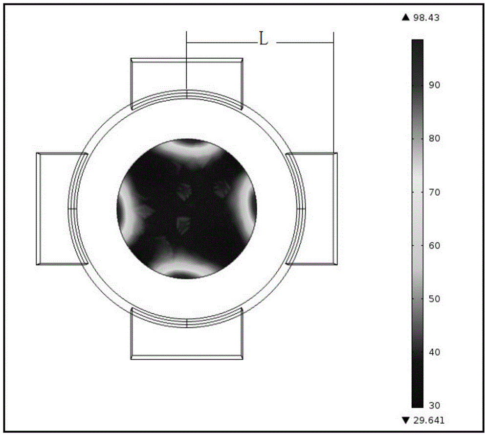
[0030] like figure 1 As shown, the cross-section of the feed-in waveguide is rectangular, and the length of the rectangle is arranged along the horizontal direction, and the width of the rectangle is arranged along the vertical direction. The distance L between the centers of A (see image 3 The mark in ) is greater than 1.1 times the length o...

Embodiment 2

[0082] The basic structure of this embodiment is the same as that of the first embodiment, and the main difference is that the number of feed-in waveguides is different.

[0083] like Figure 4 As shown, the number of feed-in waveguides in this embodiment is three (see B, C, D in the figure), and the three feed-in waveguides B, C, and D are symmetrically arranged on the side of the main resonant cavity A .

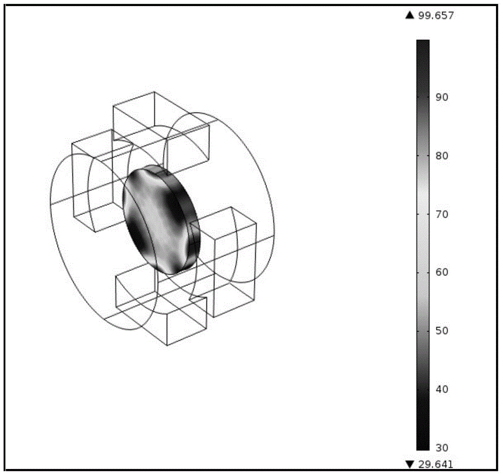
[0084] In this embodiment, the finite element analysis software COMSOL Multiphysics is used for simulation, and the establishment of the electromagnetic field and microwave energy distribution model and the thermal migration model used to calculate the heat transfer inside the wood are exactly the same as those in the first embodiment. Finally, after the finite element analysis software COMSOL Multiphysics simulation calculation, the simulated temperature distribution on the surface of the wood W when the resonant cavity of this embodiment is used to heat is obtained as f...

Embodiment 3

[0086] The basic structure of this embodiment is the same as that of the first embodiment, and the main differences are: the shape of the main resonant cavity A and the number of feeding waveguides are different. And generally speaking, the wood W is placed at the center of the main resonant cavity A, and in order to achieve uniform distribution of microwaves, the shape of the wood W is related to the shape of the main resonant cavity A, for example, the shape of the wood W in this embodiment is a cuboid, It is different from the shape of the wood W in the first embodiment which is a cylinder.

[0087] like Figure 7 As shown, the shapes of the main resonator A and the feed-in waveguide in this embodiment are both cuboid, and the number of feed-in waveguides is two (see B and C in the figure), and the two feed-in waveguides B and C are respectively Symmetrically arranged on the side of the main resonant cavity A, that is: the feeding waveguide B is arranged on one side of the...


PUM


Abstract

The invention discloses a resonant cavity for verifying wood microwave pretreatment temperature distribution. The resonant cavity for verifying wood microwave pretreatment temperature distribution comprises a main resonant cavity which is arranged horizontally; at least one fed-in waveguide is arranged on the main resonant cavity in the lateral direction; the main resonant cavity is connected with the fed-in waveguides; the fed-in waveguides are horizontally distributed along the direction from the center of the main resonant cavity to the outside; hollow-out openings are respectively formed in two end surfaces of each fed-in waveguide; the cross section of each fed-in waveguide is rectangular; the length direction of the rectangular cross section of each fed-in waveguide is a horizontal direction; the width direction of the rectangular cross section of each fed-in waveguide is a vertical direction; and the distance from the hollow-out opening of one end, which is far away from the center of the main resonant cavity, of each fed-in waveguide to the center of the main resonant cavity is 1.1 times greater than the length of the rectangular cross section of the fed-in waveguide. The resonant cavity for verifying wood microwave pretreatment temperature distribution has the advantages that wood microwave energy utilization rate is high, microwave energy is dispersed uniformly, temperature distribution uniformity is high, and wood breaking rate is low.

Description

technical field [0001] The invention relates to the technical field of microwave pretreatment of wood, in particular to a resonant cavity for verifying the temperature distribution of microwave pretreatment of wood. Background technique [0002] The area and stock volume of fast-growing plantations in my country rank first in the world, but fast-growing wood generally has defects such as poor permeability, drying and post-corrosion, and difficulty in flame-retardant treatment, so that the high value-added utilization of solid wood has not made breakthrough progress. [0003] High-intensity microwave pretreatment is a new technology that has appeared in the field of wood modification in recent years. Its basic principle is to use high-intensity microwaves to treat wet wood instantaneously, so that the moisture in the wood can obtain enough energy in a short time to produce phase change. And gas thermal pressure effect, driven by steam expansion power, destroys the internal st...

Claims


Application Information

Patent Timeline
Patent Type & Authority Applications(China)
IPC IPC(8): H05B6/64F26B23/08
Inventor 李贤军李曦罗勇锋牟群英严永林陈红斌刘凌虹王纯贺霞
Owner CENTRAL SOUTH UNIVERSITY OF FORESTRY AND TECHNOLOGY
Why Eureka
Try Eureka