Cam positioning bidirectional continuous indexing worktable

An indexing table, cam technology, applied in precision positioning equipment, manufacturing tools, large fixed members, etc., can solve problems such as inability to locate, low reliability, and low work efficiency

Inactive Publication Date: 2015-07-29
CHANGZHOU INST OF MECHATRONIC TECH
View PDF6 Cites 7 Cited by
  • Summary
  • Abstract
  • Description
  • Claims
  • Application Information

AI Technical Summary

Problems solved by technology

[0002] At present, the indexing table is the most commonly used workpiece rotary indexing part for various machine tools. The indexing of the indexing table is generally realized by the rack / gear mechanism driven by the hydraulic piston cylinder; The disadvantage of this structure is that the workbench can only perform one-way, fixed-angle indexing and positioning, and the work efficiency is low; in addition, when the pressure of the hydraulic system, the stroke of the piston cylinder and the load of the workbench change, it may cause the division If the degree is not correct, there will be a problem that the teeth of the tooth plate are topped and cannot be positioned, and its reliability is low.

Method used


Image

  • Cam positioning bidirectional continuous indexing worktable
  • Cam positioning bidirectional continuous indexing worktable
  • Cam positioning bidirectional continuous indexing worktable

Examples


Embodiment Construction

[0027] In order to make the content of the present invention more clearly understood, the present invention will be further described in detail below based on specific embodiments and in conjunction with the accompanying drawings.

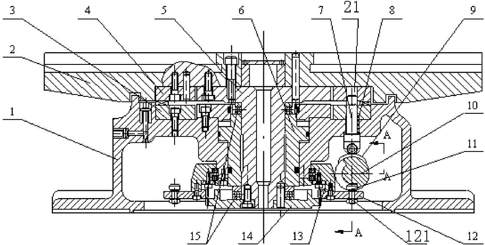
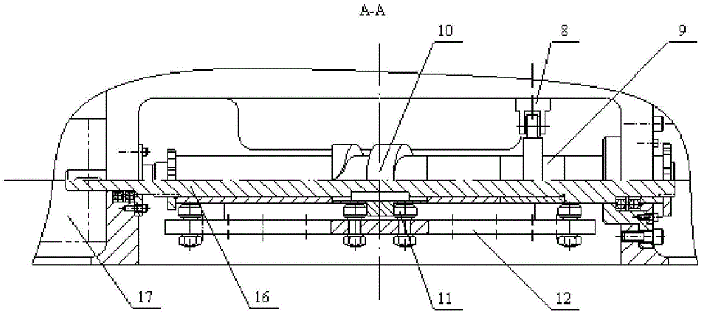
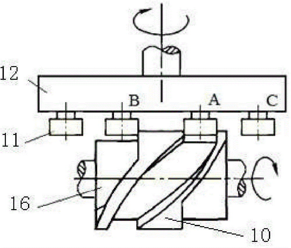
[0028] Such as Figure 1-7 As shown, a cam positioning bidirectional continuous indexing table, it includes:

[0029] A base 1, a piston cylinder is arranged in the base 1;

[0030] The table top 2 is provided with a limit assembly between the table top 2 and the base 1 to limit the relative rotational position of the table top 2 and the base 1, and the table top 2 is provided with a plurality of indexing position holes 21;

[0031] A camshaft 16, the camshaft 16 is rotatably supported on the base 1, and the outer wall of the camshaft 16 has a cylindrical cam body 10 and a plane cam body 9;

[0032] Locating pin 7, one end of locating pin 7 cooperates with a plurality of index position holes 21, and the other end of locating pin 7 abuts with plan...


PUM


Abstract

The invention discloses a cam positioning bidirectional continuous indexing worktable. The cam positioning bidirectional continuous indexing worktable comprises a base, a tabletop, a cam shaft, a positioning pin and a rotary positioning assembly, wherein the base is internally provided with a piston cylinder; a limiting assembly for limiting relative rotary positions of the tabletop and the base is arranged between the tabletop and the base; a plurality of indexing position holes are formed in the tabletop; the cam shaft is rotationally supported on the base; the outer wall of the cam shaft is provided with a cylindrical surface cam body and a plane cam body; one end of the positioning pin is matched with the plurality of indexing position holes and the other end of the positioning pin abuts against the plane cam body so that the other end of the positioning pin can be inserted into or released from the indexing position holes under the action of the plane cam body when the cam shaft rotates. Under the driving of a power source and the piston cylinder, the bidirectional continuous rotary indexing and the accurate positioning of the worktable can be automatically realized; compared with a common hydraulic indexing worktable, the problems of bidirectional continuous indexing, top tooth positioning and the like are solved; meanwhile, a gear / rack indexing mechanism is also cancelled, the indexing speed is rapid and the positioning is accurate and reliable.

Description

technical field [0001] The invention relates to a cam positioning bidirectional continuous indexing workbench, which can be widely used in various machine tools and belongs to the field of equipment manufacturing. Background technique [0002] At present, the indexing table is the most commonly used workpiece rotary indexing part for various machine tools. The indexing of the indexing table is generally realized by the rack / gear mechanism driven by the hydraulic piston cylinder; The disadvantage of this structure is that the workbench can only perform one-way, fixed-angle indexing and positioning, and the work efficiency is low; in addition, when the pressure of the hydraulic system, the stroke of the piston cylinder and the load of the workbench change, it may cause the division If the degree is not correct, there will be a problem that the teeth of the tooth plate top and cannot be positioned, and its reliability is low. Contents of the invention [0003] The technical ...

Claims


Application Information

Patent Timeline
Patent Type & Authority Applications(China)
IPC IPC(8): B23Q16/06B23Q1/52
CPCB23Q16/06B23Q1/522
Inventor 龚仲华金建平汤彩萍
Owner CHANGZHOU INST OF MECHATRONIC TECH
Why Eureka
Try Eureka