Feeding device for oil field waste treatment system and work method of feeding device

An oil field waste and treatment system technology is applied in the field of the feeding device of the oil field waste treatment system, which can solve the problems of incomplete treatment, insufficient heating of materials, and too many materials, so as to improve the efficiency and effect of treatment operations and improve work efficiency. Efficiency, the effect of improving processing efficiency

Active Publication Date: 2015-07-29
RUIJIE ENVIRONMENTAL PROTECTION TECH CO LTD
View PDF4 Cites 108 Cited by
  • Summary
  • Abstract
  • Description
  • Claims
  • Application Information

AI Technical Summary

Problems solved by technology

[0004] At present, the feeding device for feeding oilfield waste into the heating chamber is mainly a belt or screw feeder, which occupies a large area and is not suitable for oilfield waste with a large degree of liquid state, and the conveying speed and volume are difficult to control. If the speed is fast, t...

Method used


Image

  • Feeding device for oil field waste treatment system and work method of feeding device
  • Feeding device for oil field waste treatment system and work method of feeding device
  • Feeding device for oil field waste treatment system and work method of feeding device

Examples


Embodiment 1

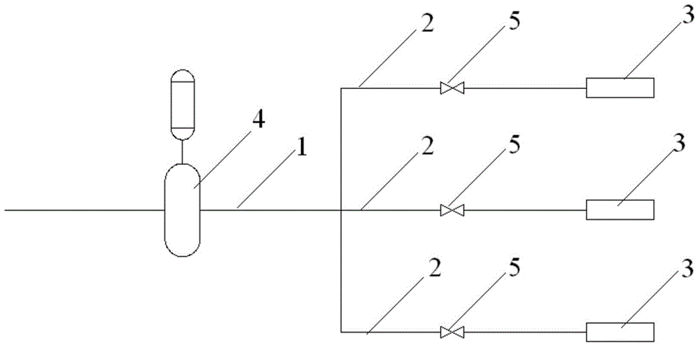
[0024] Such as figure 1 As shown, it includes a main pipe 1 and a plurality of branch pipes 2. The front ends of the branch pipes 2 are all connected to the rear end of the main pipe 1, and the rear ends of the branch pipes 2 are connected to the corresponding heating chamber 3. On the main pipe 1 A main mud pump 4 is installed, and the main mud pump 4 is a displacement pump, and branch valves 5 are installed on the branch pipes 2 .

[0025] When in use, first open the branch valve 5 on one branch pipe 2, and then close the branch valves 5 on the other branch pipes 2. The main mud pump 4 works to pump the material through the main pipe 1 to the corresponding branch pipe 2 and then into the Corresponding to the heating chamber 3.

[0026] After the main mud pump 4 runs for a set time T, close the opened branch valve 5, and then open the branch valve 5 on the next branch pipe 2, so that the material is pumped into the heating chamber 3 corresponding to the next branch pipe 2 ,...

Embodiment 2

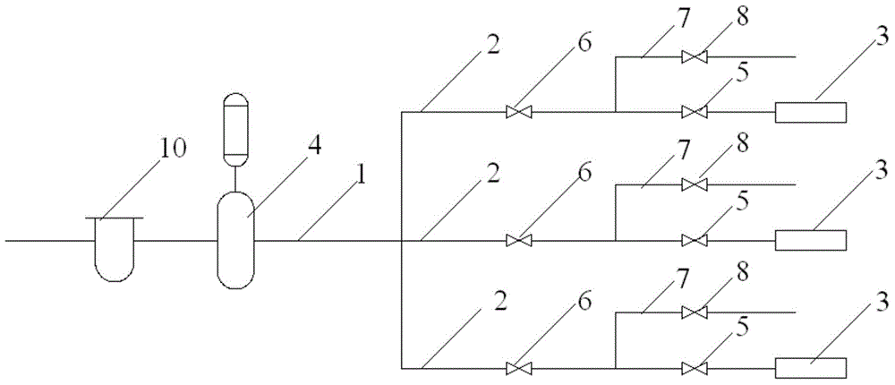
[0029] Such as figure 2 As shown, it has the same structure as that of Embodiment 1, and the different technical feature is that: the branch pipe 2 is equipped with a branch regulating valve 6, and the branch regulating valve 6 is located on the front side of the branch valve 5, and the branch A calibration pipe 7 is installed on the pipes 2, and the front end of the calibration pipe 7 is connected to the branch pipe 2. The connection point between the calibration pipe 7 and the branch pipe 2 is located between the branch regulating valve 6 and the branch valve 5. A calibration valve 8 is installed.

[0030] When in use, close the branch valve 5 of each branch pipe 2, and open the branch regulating valve 6 and calibration valve 8 on each branch pipe 2, use the main mud pump 4 to transport the material through the main pipe 1 to each branch pipe 2, and Discharge from each calibration tube 7. After each calibration tube 7 starts to discharge the material, the amount of materi...

Embodiment 3

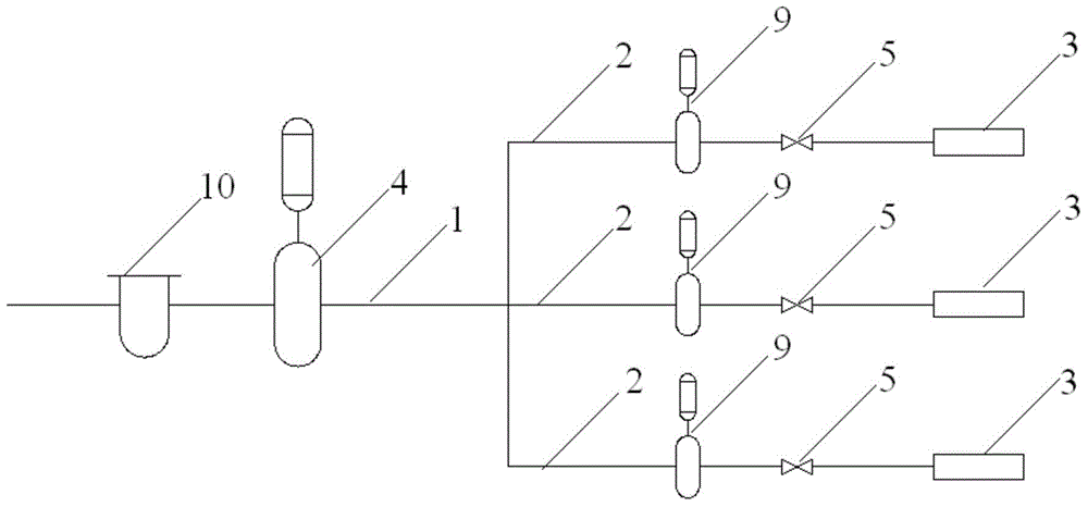
[0033] Such as image 3 As shown, it has the same structure as Embodiment 1, and the difference technical feature is that branch mud pumps 9 are installed on the branch pipes 2, and the branch mud pumps 9 are also displacement pumps, located at the side of the branch valve 5. front side.

[0034] The displacements of the branch mud pumps 9 are all the same, and are all smaller than the main mud pump 4 .

[0035] When in use, the main mud pump 4 transports the material to each branch pipe 2 through the main pipe 1, and then the branch mud pump 9 on each branch pipe 2 pumps the material into each heating chamber 3.

[0036] Since the branch mud pump 9 is a positive displacement pump, the amount of material delivered by each revolution or each stroke of its operation is constant. During the working process, the motor frequency of each branch mud pump 9 is maintained at the same value, and the displacement of the main mud pump 4 must be matched with the total intake of each bran...


PUM


Abstract

A feeding device for an oil field waste treatment system comprises a main pipe and multiple branch pipes, wherein front ends of the branch pipes are all connected with the rear end of the main pipe, and rear ends of the branch pipes are all connected with corresponding heating cavities; a main slurry pump which is a positive displacement pump is mounted on the main pipe; root valves are mounted on all of the branch pipes. The feeding device for the oil field waste treatment system adopts the positive displacement pump for pumping, materials with higher fluidity can be conveyed and distributed, and the feeding quantity can be measured, so that a proper quantity of materials are conveyed into the heating cavities, the materials are completely treated, the heat energy of a burner can be more efficiently utilized, and the treatment efficiency is improved. The materials can be constantly conveyed into the heating cavities quantitatively at a constant speed for a long time through measurement of calibration ports and regulation of branch regulation valves, the continuity of waste treatment work can be higher, and the work efficiency is further improved.

Description

technical field [0001] The invention relates to an oilfield waste treatment technology, in particular to a feeding device and a working method for the oilfield waste treatment system. Background technique [0002] With the increasing development of unconventional energy such as shale gas in the country, oilfield wastes such as waste oil-based mud and oily drilling cuttings continue to be produced and accumulated in large quantities. In oil and gas exploration, development and production, waste oil-based mud and oily drilling cuttings Improper disposal of oilfield waste, such as oilfield waste, will cause serious pollution of water resources and soil, and restrict development progress. [0003] The current processing equipment for oilfield waste treatment mainly sends oilfield waste into the heating chamber through the feeding device, and the heating chamber is placed in the combustion chamber. The air and the shell of the heating chamber perform convective heat exchange, in...

Claims


Application Information

Patent Timeline
IPC IPC(8): C02F11/00C02F11/10
Inventor 叶登胜宫晓伟冷欣奇喻学孔陈开军林慧丽梁仁刚张建伟李率钊
Owner RUIJIE ENVIRONMENTAL PROTECTION TECH CO LTD
Why Eureka
Try Eureka