Self-grinding gas pipeline seal seat valve for high temperature and dust environments

A gas pipeline, self-grinding technology, applied in the direction of valve lift, valve details, valve device, etc., can solve the problems of purchase cost, use cost increase, contact surface and valve disc are not tightly matched, not resistant to high temperature, etc., to reduce heat Dissipation, avoid rigid hard wear, and achieve the effect of contact

Active Publication Date: 2015-07-29
XIXIA LONGCHENG SPECIAL MATERIALS CO LTD
View PDF5 Cites 6 Cited by
  • Summary
  • Abstract
  • Description
  • Claims
  • Application Information

AI Technical Summary

Problems solved by technology

[0002] In the gas pipeline valves for dust in high-temperature environments, due to the inclusion of a large amount of dust, the sealing of the on-off control parts of the high-temperature gas system pipelines here is particularly important. The traditional control method generally uses a disc-type globe valve; Dust particles make it impossible to achieve long-term effective sealing between the valve disc and the valve seat; secondly, it is easy to wear and cannot withstand high temperatures; and the sealing performance is poor, requiring frequent maintenance and replacement, resulting in increased purchase and use costs, and the effect has not been good. good
[0003] In addition, in the existing globe valve, the contact surface between the valve seat and the disc is usually set as a large plane, and the two hard planes are in contact with each other to seal. Or impurit

Method used


Image

  • Self-grinding gas pipeline seal seat valve for high temperature and dust environments
  • Self-grinding gas pipeline seal seat valve for high temperature and dust environments
  • Self-grinding gas pipeline seal seat valve for high temperature and dust environments

Examples


Embodiment Construction

[0034] name Sealing cycles (number of times) Outlet air flow after sealing (with / without) Plate valve 3-5 Have This device 10000-11000 none

[0035] It can be seen from the above table that for the same high-temperature dust environment, under the same caliber and air flow, the sealing cycle of this device is increased by more than 2000 times compared with the common high-temperature dust valve body, and there is no air leakage after sealing, while the common Due to the presence of dust, the plate valve is not tightly sealed and leaks.

[0036] name Sealing cycles (opening and closing times) Cleaning mechanism not used 10-20 Cyclone airflow 20-30 The cleaning mechanism of this device 10000-11000

[0037] As can be seen from the table above, the adoption of different cleaning mechanisms in the present invention and the absence of cleaning mechanisms will seriously affect the sealing cycles of the present invent...


PUM


Abstract

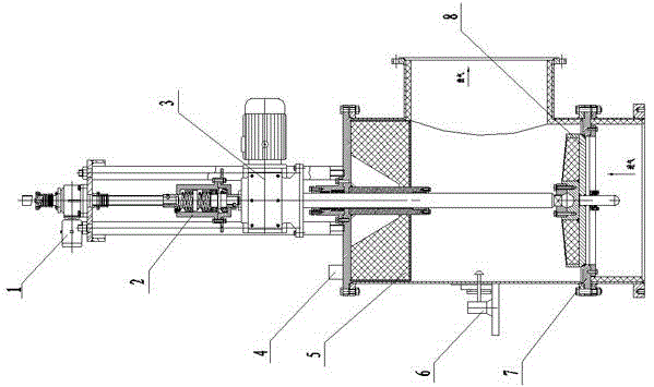
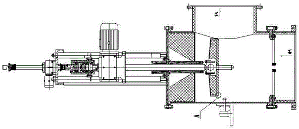
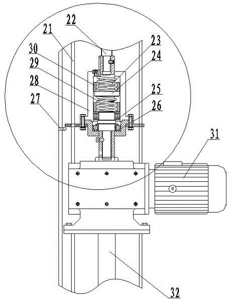
The invention discloses a self-grinding gas pipeline seal seat valve for high temperature and dust environments. The self-grinding gas pipeline seal seat valve comprises a valve casing body, a lifting mechanism, a suspension mechanism, a rotation driving mechanism, a sweeping mechanism, a valve core and a seal ring; the lifting mechanism is connected with a valve rod; the valve rod is connected with the suspension mechanism; the lower part of the suspension mechanism is provided with the rotation driving mechanism; the lower part of the rotation driving mechanism penetrates through the valve casing body through a rotary valve rod and is connected with the valve core; the seal ring is arranged at an air inlet in the lower part of the valve casing body; the sweeping mechanism is arranged at the side wall of the valve casing body; a control mechanism is connected with the lifting mechanism, the rotation driving mechanism and the sweeping mechanism. The problem of the seal stop of a valve body under the high temperature and dust environments is solved, so that the seal valve is prolonged to 11 thousand times of opening and closing from several times after which the seal valve can lose efficacy after being opened and closed originally; moreover, the self-grinding gas pipeline seal seat valve disclosed by the invention has an excellent seal effect; after the self-grinding gas pipeline seal seat valve is closed, zero leakage is realized; the equipment replacing frequency is reduced; production can be smoothly performed; the self-grinding gas pipeline seal seat valve is worthy of being applied and popularized.

Description

technical field [0001] The invention relates to the technical field of valves, in particular to a gas pipeline sealing seat valve for self-grinding high-temperature dust environments. Background technique [0002] In the gas pipeline valves for dust in high-temperature environments, due to the inclusion of a large amount of dust, the sealing of the on-off control parts of the high-temperature gas system pipelines here is particularly important. The traditional control method generally uses a disc-type globe valve; Dust particles make it impossible to achieve long-term effective sealing between the valve disc and the valve seat; secondly, it is easy to wear and cannot withstand high temperatures; and the sealing performance is poor, requiring frequent maintenance and replacement, resulting in increased purchase and use costs, and the effect has not been good. good. [0003] In addition, in the existing globe valve, the contact surface between the valve seat and the d...

Claims


Application Information

Patent Timeline
IPC IPC(8): F16K1/32F16K31/04F16K1/00
CPCF16K1/00F16K1/32F16K1/36F16K31/04F16K31/047
Inventor 朱书成赵家亮黄国团王博
Owner XIXIA LONGCHENG SPECIAL MATERIALS CO LTD
Why Eureka
Try Eureka