Roller kiln and working method thereof

A technology of roller kiln and kiln roof, applied in combustion method, furnace type, waste heat treatment, etc., can solve the problems of low utilization rate of waste heat of roller kiln, poor production environment, high cost, and reduce investment cost and maintenance and repair cost. , The effect of short conveying distance and reducing operating costs

Inactive Publication Date: 2015-07-29
HUNAN OTLAN IND EQUIP
View PDF4 Cites 0 Cited by
  • Summary
  • Abstract
  • Description
  • Claims
  • Application Information

AI Technical Summary

Problems solved by technology

[0010] In order to solve the technical problems of low waste heat utilization rate, high cost and poor production environment of the roller kiln in the prior art, the present invention discloses a roller kiln with high waste heat utilization rate, low cost and good production environment and its working method

Method used


Image

  • Roller kiln and working method thereof
  • Roller kiln and working method thereof
  • Roller kiln and working method thereof

Examples


Embodiment Construction

[0041] The following will clearly and completely describe the technical solutions in the embodiments of the present invention. Obviously, the described embodiments are only some of the embodiments of the present invention, rather than all the embodiments. Based on the embodiments of the present invention, all other embodiments obtained by persons of ordinary skill in the art without making creative efforts belong to the protection scope of the present invention.

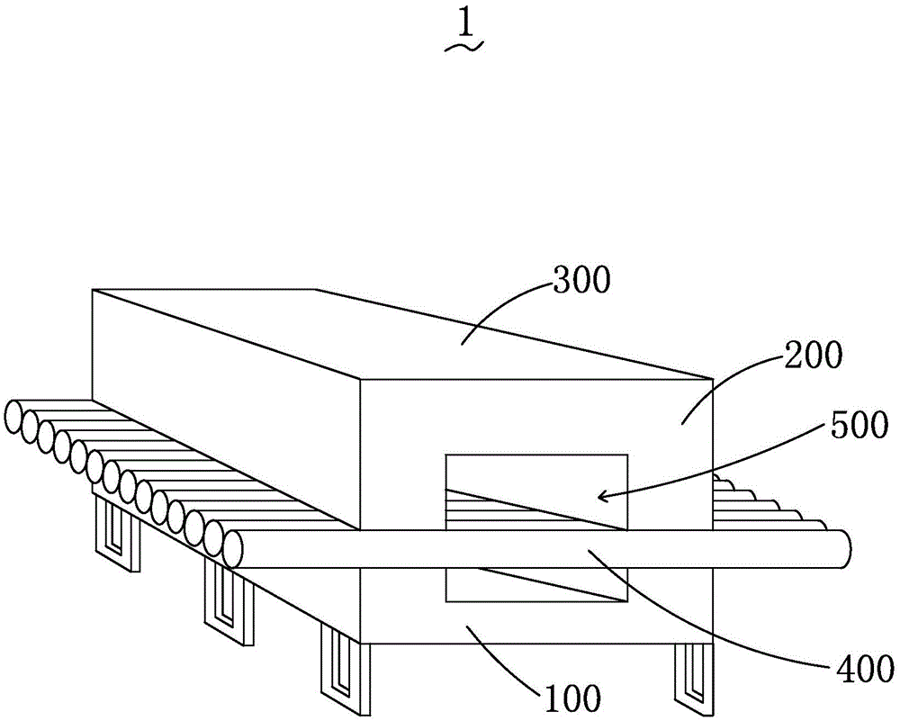
[0042] see figure 1 , is a schematic diagram of the three-dimensional structure of the roller kiln provided by the present invention. The roller kiln 1 includes a kiln bottom 100, a side wall 200, a kiln roof 300, and a transmission roller device 400, and two opposite side walls 200 are sandwiched between the kiln roof 300 and the kiln bottom 100 It also encloses a kiln storage space 500 with openings at both ends. The transmission roller device 400 is connected to two oppositely arranged side walls 200. The transmi...


PUM


Abstract

The invention provides a roller kiln and a working method thereof. The roller kiln comprises an injection mixer, a high temperature waste heat air duct, an injection burner and a waste heat air system; the roller kiln is divided into a preheating section, a firing section and a cooling section along the direction of movement of products; the injection mixer is arranged on the cooling section; the injection burner is arranged on the firing section; the high temperature waste heat air duct is communicated with the cooling section and the firing section; the waste heat air system is arranged at the top of the firing section and the top of the cooling section; the injection mixer is of a concealed venturi tube structure and the injection burner is of a concealed venturi tube structure. According to the roller kiln and the working method thereof, the injection mixer which is of a venturi tube structure is added into the roller kiln so as to directly suck the high temperature waste heat air of a cooling zone of the roller kiln to be pressurized and conveyed to the injection burner of a firing zone and accordingly the high temperature waste heat is well utilized, the sufficient burning is ensured, the energy is saved, and the production workshop environment is improved.

Description

technical field [0001] The invention relates to the field of industrial kilns, in particular to a roller kiln and a working method thereof. Background technique [0002] As we all know, the higher the temperature of the combustion-supporting gas in the roller kiln, the more energy-saving it will be. Therefore, it is undoubtedly the most effective method to use the waste heat of the roller kiln to increase the temperature of the supporting gas. The waste heat of the roller kiln is mainly formed by the air that the cooling fan blows into the kiln to cool the product and absorbs the heat of the fired product after contact. [0003] In the prior art, there are two main methods for utilizing the waste heat in the cooling section of the roller kiln: [0004] The first is by setting a heat exchanger in the cooling section of the roller kiln; [0005] The second is to use a high-power high-temperature fan to extract the residual hot air in the cooling section after mixing the cold...

Claims


Application Information

Patent Timeline
Patent Type & Authority Applications(China)
IPC IPC(8): F27B9/12F27B9/30F27B9/36F27D17/00F23L15/00
CPCY02E20/34
Inventor 冯伟张旭
Owner HUNAN OTLAN IND EQUIP
Why Eureka
Try Eureka