Light emitting diode (LED) packaging technology based on silver alloy wires

A technology of LED packaging and silver alloy, which is applied in the direction of semiconductor devices, electrical components, circuits, etc., can solve the problems of point B breakage, mechanical performance degradation, and coarse grains, etc., and achieve the effects of increased brightness, low price, and good reflective properties

Inactive Publication Date: 2015-07-29
CHANGZHI HONGYUAN PHOTOELECTRIC TECH
View PDF5 Cites 2 Cited by
  • Summary
  • Abstract
  • Description
  • Claims
  • Application Information

AI Technical Summary

Problems solved by technology

[0003] In the existing LED packaging process, silver wire or gold wire is usually used as the bonding wire. Due to the

Method used


Image

  • Light emitting diode (LED) packaging technology based on silver alloy wires

Examples


Embodiment 1

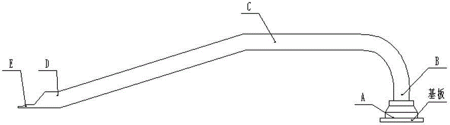
[0017] Such as figure 1 As shown, a kind of LED packaging process based on silver alloy wire is carried out according to the following steps:

[0018] 1) Raw material preparation: Ultrasonic cleaning of the LED bracket, drying, and then thawing the crystal-bonding glue;

[0019] 2) Die-bonding production: place the LED chip on the LED bracket coated with die-bonding glue;

[0020] 3) Die-bonding adhesive baking: Send the LED bracket into the baking station for the die-bonding adhesive to bake, so that the LED chip is fixed on the LED bracket, and the thrust test is performed after the die-bonding adhesive is baked;

[0021] 4) Welding wire: Use a silver alloy wire to electrically connect the positive and negative poles of the LED chip and the positive and negative poles of the LED bracket on the wire bonding machine. The gold content in the alloy wire is 8%, and the silver content is 89%. The diameter of the wire is 0.9mil, the bonding parameters of the LED chip and the allo...

example 2

[0027] A kind of LED encapsulation technology based on silver alloy wire, carries out according to the following steps:

[0028] 1) Raw material preparation: Ultrasonic cleaning of the LED bracket, drying, and then thawing the crystal-bonding glue;

[0029] 2) Die-bonding production: place the LED chip on the LED bracket coated with die-bonding glue;

[0030] 3) Die-bonding adhesive baking: Send the LED bracket into the baking station for the die-bonding adhesive to bake, so that the LED chip is fixed on the LED bracket, and the thrust test is performed after the die-bonding adhesive is baked;

[0031] 4) Welding wire: Use a silver alloy wire to electrically connect the positive and negative poles of the LED chip to the positive and negative poles of the LED bracket on the wire bonding machine. The gold content in the alloy wire is 7-9%, and the silver content is 88-90% %, the diameter of the silver alloy wire is 0.9mil, the bonding parameters of the LED chip and the alloy wi...

Embodiment 3

[0036] A kind of LED encapsulation technology based on silver alloy wire, carries out according to the following steps:

[0037] 1) Raw material preparation: Ultrasonic cleaning of the LED bracket, drying, and then thawing the crystal-bonding glue;

[0038] 2) Die-bonding production: place the LED chip on the LED bracket coated with die-bonding glue;

[0039] 3) Die-bonding adhesive baking: Send the LED bracket into the baking station for the die-bonding adhesive to bake, so that the LED chip is fixed on the LED bracket, and the thrust test is performed after the die-bonding adhesive is baked;

[0040] 4) Welding wire: Use a silver alloy wire to electrically connect the positive and negative poles of the LED chip to the positive and negative poles of the LED bracket on the wire bonding machine. The gold content in the alloy wire is 7-9%, and the silver content is 88-90% %, the diameter of the silver alloy wire is 0.9mil, the bonding parameters of the LED chip and the alloy wi...


PUM


Abstract

The invention belongs to the field of light emitting diode (LED) packaging, particularly discloses an LED packaging technology based on silver alloy wires and provides an LED packaging process based on the silver alloy wires. An LED wafer that is manufactured by the packaging process is good in light reflecting performance, light absorption is absent, and the price is lower than that of traditional gold wires. The packaging technology includes steps of (1) raw material preparation, (2) solid crystal production, (3) solid crystal glue baking, (4) wire welding, (5) glue dispensing and (6) baking, wherein the step (4) includes that positive and negative poles of the LED wafer are electrically connected with positive and negative poles of an LED support on a wire welding machine through the silver alloy wires, the gold content in the alloy wires is 7%-9%, the silver content in the alloy wires is 88%-90%, the diameter of the silver alloy wires is 0.9mil, bonding parameters of the LED wafer and the alloy wires include that the welding power is 20-50mw, the welding pressure is 20-50gms, welding time is 10-20ms and the bonding area temperature is 150-170 DEGC, and tensile test is performed after wire welding.

Description

technical field [0001] The invention belongs to the field of LED packaging, in particular to an LED packaging process based on silver alloy wires. Background technique [0002] At present, the welding wire of LED packaging is to use ultrasonic (60-120KHz) generator to cause horizontal elastic vibration of the chopper and apply downward pressure at the same time. Under the action of these two forces, the chopper drives the lead wire to rub rapidly on the metal surface of the welding area, and then the surface oxide layer is abraded, and the lead wire undergoes plastic deformation under the action of energy, and the lead wire is in close contact with the bonding area to form a weld within 25ms. In addition, an external heat source is required to activate the energy level of the material, promote the effective connection of the two metals and the diffusion and growth of the intermetallic compound (IMC). [0003] In the existing LED packaging process, silver wire or gold wire i...

Claims


Application Information

Patent Timeline
IPC IPC(8): H01L33/20H01L33/62H01L33/52
CPCH01L33/48H01L33/62H01L2933/0066H01L2933/0033H01L24/45H01L2224/45139H01L2224/48465H01L2224/45144H01L2924/00011H01L2224/45015H01L2224/45H01L2924/00H01L2924/01049H01L2924/01079H01L2924/20752H01L2924/00012H01L2924/01005
Inventor 徐龙飞
Owner CHANGZHI HONGYUAN PHOTOELECTRIC TECH
Why Eureka
Try Eureka