Hydraulic jet air cyclone

A technology of hydraulic jet and cyclone, applied in the field of chemical engineering, can solve problems such as unreasonable design, and achieve the effects of enhanced gas-liquid coupling effect, high gas-liquid mass transfer efficiency, and high mass transfer efficiency

Inactive Publication Date: 2015-08-05
CHONGQING UNIV OF TECH
View PDF7 Cites 9 Cited by
  • Summary
  • Abstract
  • Description
  • Claims
  • Application Information

AI Technical Summary

Problems solved by technology

However, there are still unreasonable places in the de

Method used


Image

  • Hydraulic jet air cyclone
  • Hydraulic jet air cyclone
  • Hydraulic jet air cyclone

Examples


Embodiment 1

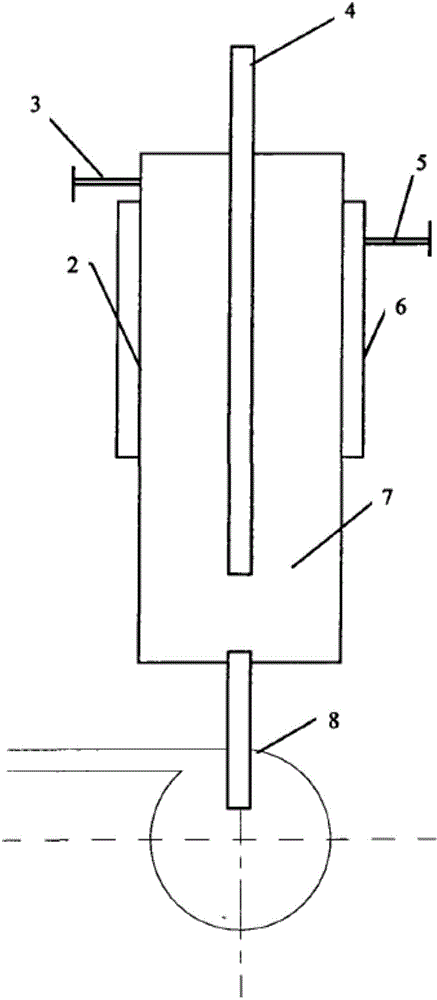
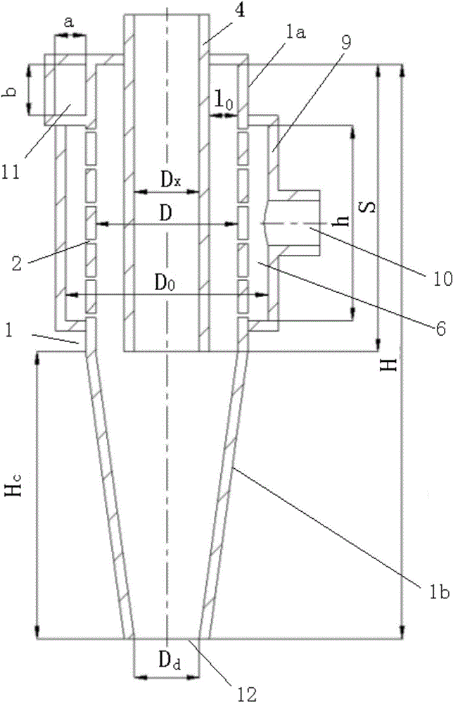
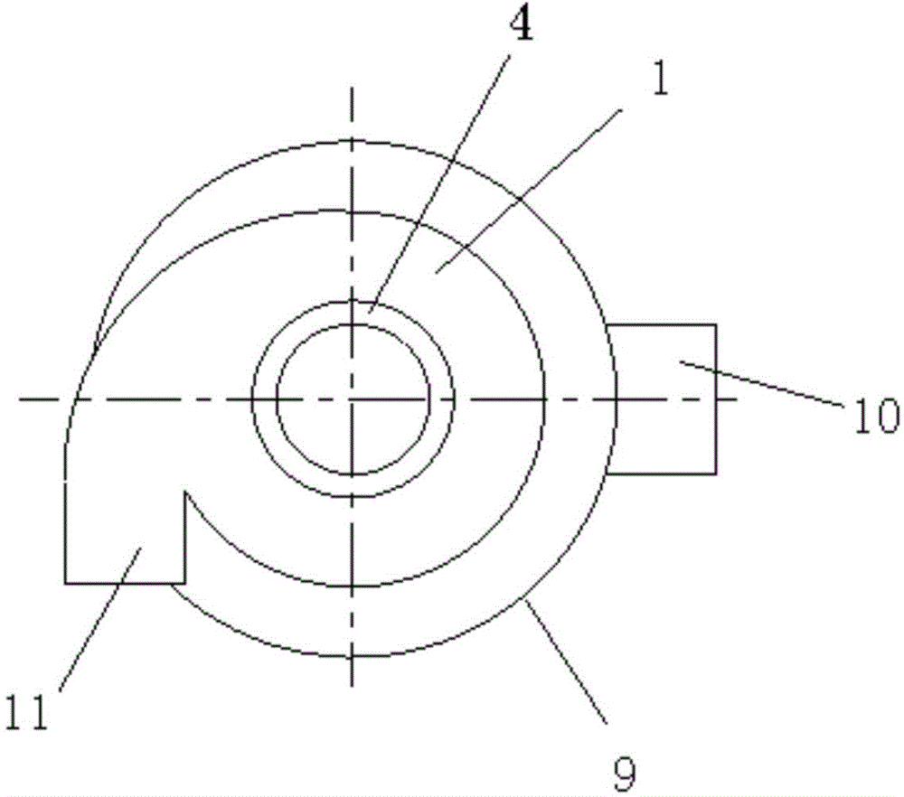
[0031] Such as figure 2 with image 3 The hydrojet air cyclone shown includes an air cyclone and a hydrojet atomization chamber 6. The air cyclone is composed of a central exhaust pipe 4 and a cyclone cylinder 1 set. The upper end of the central exhaust pipe 4 Extending out of the cyclone cylinder 1, the lower end is lower than the lower end of the hydro-jet atomization chamber 6. The cyclone cylinder 1 is provided with a swirl port 11, and the swirl port 11 is connected to the cyclone cylinder 1. Compressed gas is input inside, and the compressed gas rotates at high speed in the cyclone cylinder 1 to form a gas swirl field. There is a cylindrical outer jacket 9 on the periphery of the upper part of the cyclone cylinder 1, which is connected with the cyclone cylinder 1 The outer wall of the hydro-jet atomization chamber 6 is connected to form a hydro-jet atomization chamber 6, and a plurality of spray holes 2 are opened from top to bottom on the outer wall of the part of the...

Embodiment 2

[0050] Such as Figure 12 For the hydrojet air cyclone shown, the cyclone body 1 can also be a cylindrical body. All the other are the same as the first embodiment.


PUM

PropertyMeasurementUnit
The inside diameter ofaaaaaaaaaa

Abstract

The invention discloses a hydraulic jet air cyclone. The hydraulic jet air cyclone comprises an air cyclone and a hydraulic jet atomizing chamber, wherein the air cyclone is formed by coating a center exhaust pipe with a cyclone cylinder; the upper end of the center exhaust pipe extends outside the cyclone cylinder, and the lower end is lower than the lower end of the hydraulic jet atomizing chamber; a cyclone port is formed in the cyclone cylinder; a cylindrical outer jacket is arranged at the periphery of the upper part of the cyclone cylinder, and is connected with the outer wall of the cyclone cylinder to form the hydraulic jet atomizing chamber; multiple spraying holes are formed in the outer wall of the connected cyclone cylinder from top to bottom; a liquid inlet is formed in the upper part of the hydraulic jet atomizing chamber; a diameter Dx of the center exhaust pipe is 0.5-0.6 d mm; an insertion depth S of the center exhaust pipe is 0.5-0.75H mm; the multiple spraying holes are arranged on the outer wall of the cylindrical cylinder in a square array form; and a length h of the spraying hole area is 0.6-1S mm. The hydraulic jet air cyclone can realize high-efficiency mass transfer of gas and liquid.

Description

technical field [0001] The invention belongs to the technical field of chemical engineering, and in particular relates to a hydrojet air cyclone. Background technique [0002] Traditional gas-liquid mass transfer equipment mainly includes packed towers, plate towers and spray towers. The liquid phase flows from top to bottom under the action of gravity field, and the gas phase flows from bottom to top. Gas-liquid mass transfer occurs. However, due to the weak gravity field, the flow rate of the liquid film is low, the thickness is large, the mass transfer efficiency of the liquid film is low, and the air resistance is also high, which makes the equipment bulky, material consumption, high investment, and high operating costs. [0003] Chinese patent document CN 101147894 B discloses a hydro-jet air cyclone separator, which mainly includes an outer main cylinder 7 and a spray hole 2 on it, a waste water jacket, a hydro-jet atomization chamber 6, and a central exhaust pipe 4 ...

Claims


Application Information

Patent Timeline
IPC IPC(8): B04C5/04B04C5/08B04C5/14
Inventor 全学军程治良徐飞邱发成代明星罗丹
Owner CHONGQING UNIV OF TECH
Why Eureka
Try Eureka