
Restrained induction heating electromagnetic riveting device and method

An induction heating and electromagnetic riveting technology, which is applied in the field of constrained induction heating electromagnetic riveting devices, can solve the problems of heat conduction damage to composite materials, rivet head cracking riveting force, and rivets with upset heads, etc., to reduce damage caused by excessive temperature , high forming efficiency, and the effect of improving riveting quality

Inactive Publication Date: 2015-08-05
FUZHOU UNIVERSITY
View PDF7 Cites 26 Cited by
  • Summary
  • Abstract
  • Description
  • Claims
  • Application Information

AI Technical Summary

Problems solved by technology

First of all, due to the limited forming force of pneumatic riveting, it is still difficult to form rivets with larger diameters even if induction heating is used to reduce the material yield limit; Head rivets; again, the induction heating coil heats the entire rivet. When the riveted plate is a composite material, the heat conduction of the rivet will damage the composite material
[0004] The newly emerging electromagnetic riveting technology, based on the eddy current repulsion force generated by electromagnetic induction, can form rivets at one time. Although it has advantages in forming force and rivet interference, the riveting force is still relatively small compared with hydraulically driven equipment. For materials that are difficult to form and have poor plasticity, cracking of the rivet head and insufficient riveting force may also occur

Method used


Image

  • Restrained induction heating electromagnetic riveting device and method
  • Restrained induction heating electromagnetic riveting device and method
  • Restrained induction heating electromagnetic riveting device and method

Examples


Embodiment Construction

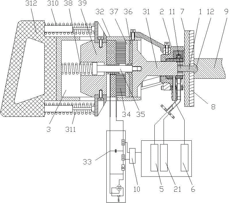
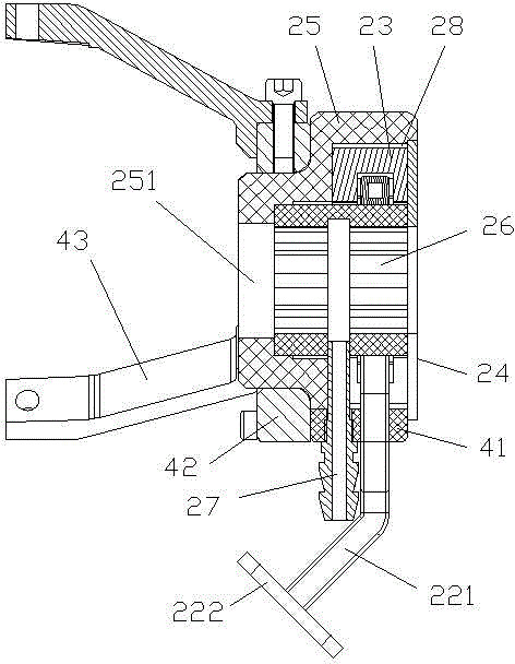
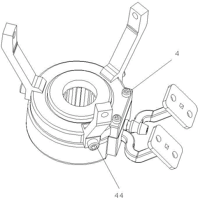
[0034] Such as Figure 1~9As shown, a constrained induction heating electromagnetic riveting device includes a constrained induction heater 2 for quickly heating the head 11 of the rivet 1 to be formed. The heating coil 22, the induction heating coil 22 is provided with a number of ferrites 23 for confining the magnetic field, and the confinement induction heater 2 also includes a set of ferrites 23 arranged outside the induction heating coil 22 and the ferrite 23 The silicon steel sheet 24 that shields the leakage magnetic field, the restraint induction heater 2 is sleeved at the end of the amplifier 31 of the electromagnetic riveting gun 3 and is fixedly connected with the shell of the electromagnetic riveting gun 3 through the support frame 4, and the amplifier 31 is relatively bound to the induction heater 2 Movement to form the head 11 of the heated rivet 1 to be formed.

[0035] In the present invention, the support frame 4 includes a support plate 41 fixed on the two p...


PUM


Abstract

The invention relates to a restrained induction heating electromagnetic riveting device, comprising a restrained induction heater for quickly heating a rivet head to be formed, wherein the restrained induction heater comprises an induction heating coil connected with a high-frequency current generating power supply, and a plurality of ferrites for restraining a magnetic field are annularly arranged on the induction heating coil; the restrained induction heater also comprises a silicon steel sheet arranged on the outer sides of the induction heating coil and the ferrites for shielding the leaked magnetic field, the restrained induction heater sleeves the tail end of the amplifier of an electromagnetic riveter and is fixedly connected with the shell of the electromagnetic riveter by a support frame, the amplifier moves with respect to the restrained induction heater to form a heated rivet head to be formed; the invention also relates to restrained induction heating electromagnetic riveting method. According to the restrained induction heating electromagnetic riveting device, the rivet is quickly heated by the restrained magnetic field, and meanwhile a composite board is not damaged; the restrained induction heater is reasonably combined with the electromagnetic riveter, so that the restrained induction heating electromagnetic riveting device is high in forming efficiency, simple in technology and applicable to the structure with poor openness.

Description

technical field [0001] The invention relates to a constrained induction heating electromagnetic riveting device and method. Background technique [0002] As a common mechanical connection method, rivet connection is widely used in various fields. At present, aerospace products are developing in the direction of large-scale and lightweight, and more and more composite material structures and high-strength large-diameter rivets are used. [0003] Traditional riveting methods include: air riveting, pressure riveting and hot riveting, etc. The forming force of air riveting is small, and the pressure riveting is limited by the openness of the structure, and hot riveting is easy to cause damage to the composite material. Chinese Invention Patent Publication No. CN1887475A, including tubular skeleton, heating coil, rivet fixing clip, spring, magnetic strip, pneumatic riveting gun, forming head and connecting cable; the forming method of electromagnetic induction heating combined ...

Claims


Application Information

Patent Timeline
IPC IPC(8): B21J15/24B21J15/28
CPCB21J15/24B21J15/08B21J15/28B21J15/38
Inventor 邓将华程溧黄伍平
Owner FUZHOU UNIVERSITY
Features
  • Generate Ideas
  • Intellectual Property
  • Life Sciences
  • Materials
  • Tech Scout
  • Unparalleled Data Quality
  • Higher Quality Content
  • 60% Fewer Hallucinations
Learn More