Sand mold plunge milling processing method and plunge milling equipment

A sand molding and plunge milling technology, applied in metal processing equipment, casting molding equipment, casting molds, etc., can solve the problems of long processing time and reduce tool service life, and achieve increased equipment service life, reduced tool wear, and strength. high effect

Active Publication Date: 2016-09-07
鞍山千钢机械制造有限公司
View PDF6 Cites 0 Cited by
  • Summary
  • Abstract
  • Description
  • Claims
  • Application Information

AI Technical Summary

Problems solved by technology

This kind of processing method has relatively longer processing time and man-hours for large castings, and reduces tool life

Method used


Image

  • Sand mold plunge milling processing method and plunge milling equipment
  • Sand mold plunge milling processing method and plunge milling equipment
  • Sand mold plunge milling processing method and plunge milling equipment

Examples


Embodiment Construction

[0033] The specific embodiment of the present invention is further described below in conjunction with accompanying drawing:

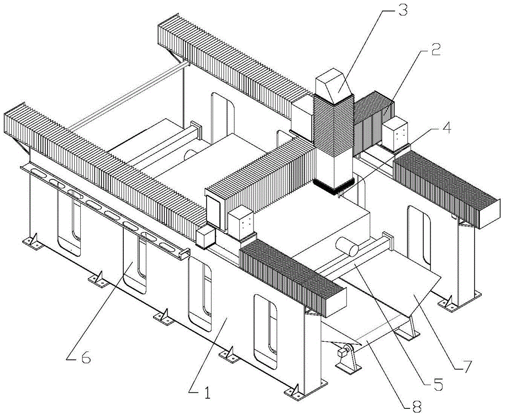
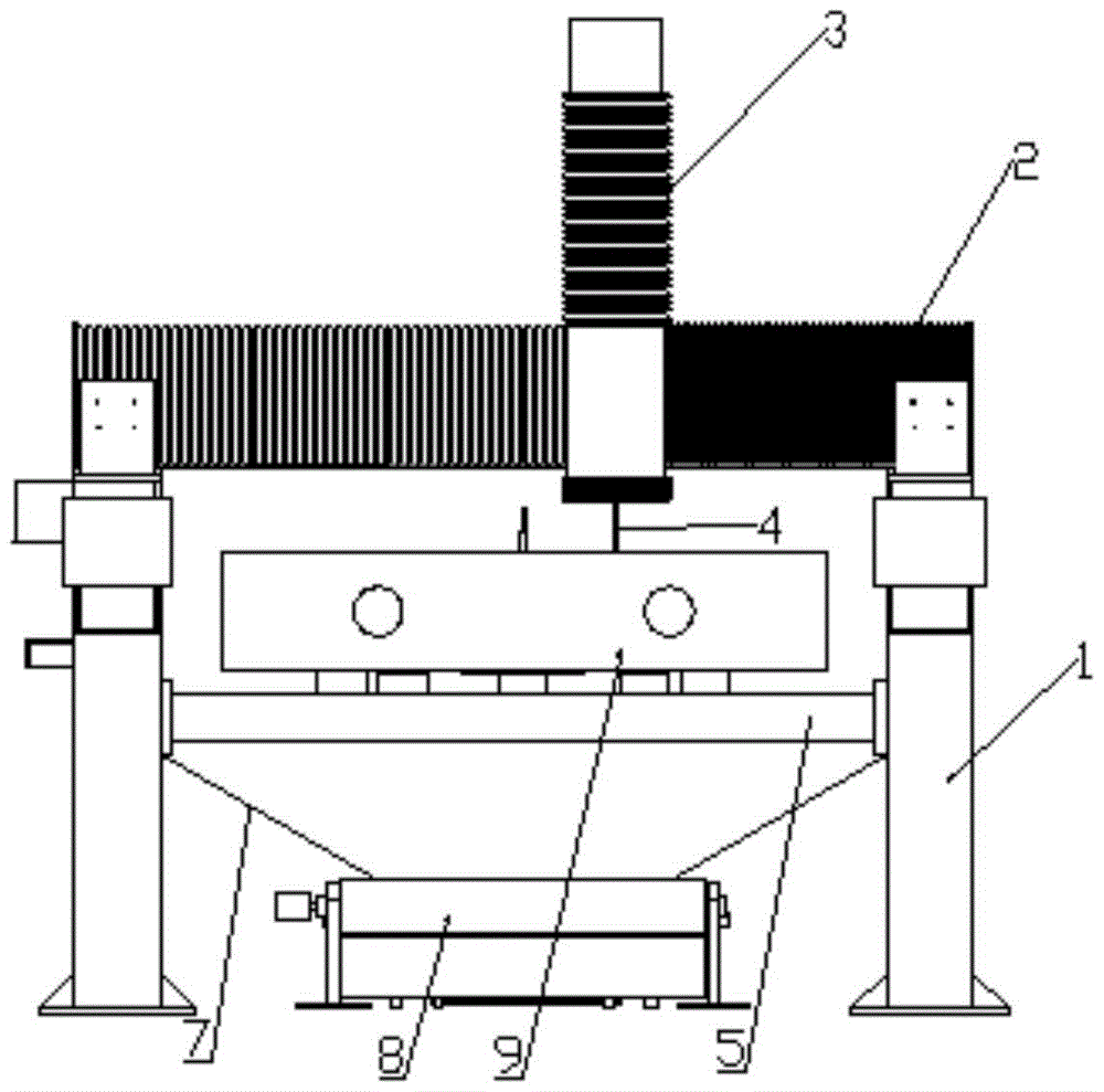
[0034] Such as figure 1 , figure 2 As shown, the sand mold inserting and milling equipment includes Y-axis wallboard 1, X-axis beam 2, Z-axis column 3, Y-axis wallboard 1 is set on both sides of X-axis beam 2, and X-axis beam 2 is set on two Y-axis Above the wall panel 1, the X-axis beam 2 is provided with a Z-axis column 3, and the Z-axis column 3 is provided with a tool 4. A plurality of viewing windows 6, a waste sand collection sloping plate 7 and a sand discharge device 8 are arranged under the workbench 5. The distance between the workbench 5 and the sand discharge device 8 is 200mm-800mm.

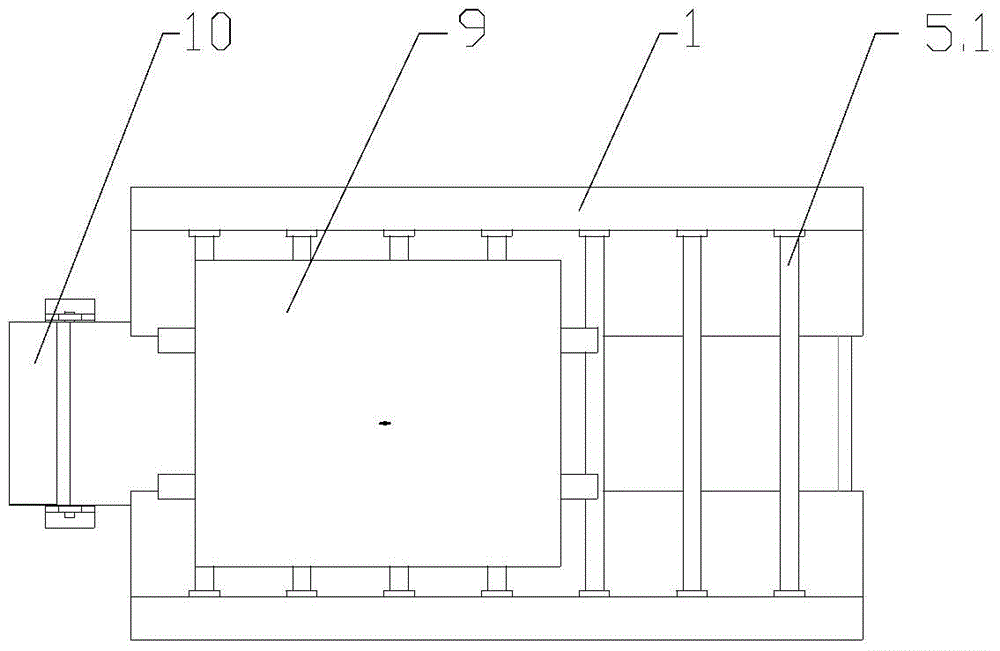
[0035] Such as image 3 As shown, the workbench 5 is a beam structure, and a plurality of beams 5.1 are arranged in parallel to form a working plane. The two ends of the beams 5.1 are fixed on the Y-axis wallboard 1, and the distance between the beams 5....


PUM


Abstract

The invention relates to a sand mold plunge milling machining method and a plunge milling device. A middle sand mold for casting is machined by the plunge milling method. The phenomenon of cutter clamping by accumulation of waste sand that is generated during transverse feeding and cutting can be avoided by the plunge milling machining method, cutter abrasion is reduced, and the phenomenon of cutter cracking is avoided. A cutter starting hole is pre-reserved in a sand core so that plunge milling machining time and cutter abrasion can be reduced. A lifting ring is pre-buried in the sand core so that the sand core can be lifted and carried away after machining of the sand core is finished, the problem of sand core damage due to only lifting of the sand mold during traditional machining is avoided, and defects of repositioning of secondary clamping, wasting work hours and the like are avoided. The sand core can be intactly maintained and reused by the plunge milling machining method. A working table of the plunge milling device is in a transverse beam structure so that sand discharging is convenient, and dust pollution caused by sand discharging of compressed air is avoided. The distance between the working table and a sand discharging device is long so that sand discharging is facilitated. The plunge milling device is high in strength and quite suitable for machining of large sand molds.

Description

technical field [0001] The invention relates to the field of moldless casting sand mold processing, in particular to a sand mold plunge-milling processing method and plunge-milling equipment. Background technique [0002] Casting is an ancient manufacturing method. With the development of industrial technology, many new casting methods have emerged, such as low-pressure casting, ceramic casting, continuous casting, investment casting, precision casting, special casting, etc. The conditions of use of these casting methods High requirements, high production costs, large amount of machining, poor working conditions, low productivity and other shortcomings, and the range of casting applications is limited due to its casting characteristics. [0003] For the production and processing of large castings, sand casting is still the main method. However, the traditional casting process did not meet the requirements, and the manufacturing process of wooden molds and metal molds was ti...

Claims


Application Information

Patent Timeline
Patent Type & Authority Patents(China)
IPC IPC(8): B22C23/00B22C9/02B22C9/10
Inventor 鲍壮鲍猛李迎昀
Owner 鞍山千钢机械制造有限公司
Why Eureka
Try Eureka