Nickel ore sintering machine

A sintering machine and nickel ore technology, applied in the field of nickel ore processing equipment, can solve the problems of heat energy loss, increased heat loss, large discharge particle size, etc. Effect

Active Publication Date: 2015-08-05
连云港泓聚莱釉料有限公司
View PDF4 Cites 6 Cited by
  • Summary
  • Abstract
  • Description
  • Claims
  • Application Information

AI Technical Summary

Problems solved by technology

[0002] At present, the shaft kiln used in China's cement industry is in the form of a single-tower grate ring discharge, and the kiln body of the shaft kiln is straight. "Excess, so that the coal in the ball is burned unevenly, resulting in a large loss of heat energy, low clinker quality, reduced output, and reduced labor production efficiency, and the tower grate of the large-diameter shaft kiln is bulky, making it difficult to manufacture and install , the normal firing and unloading of the clinker in the kiln cannot be guaranteed, the fixed jaw plate wears quickly, the replacement cycle is short, the discharge particle size is large, and the discharge temperature is high, which further increases the heat loss; secondly, in the nickel ore production process The exhaust gas produced passes through the two exhaust pipes on the top of the kiln body, and then is discharged directly through a vertical chimney. In order to reduce the pollution of the exhaust gas, the height of the chimney is generally set at 50-100 meters. High, which puts forward higher requirements on the power of exhaust emission, which makes the exhaust emission efficiency low, the emission is not clean, and it is easy to cause part of the exhaust gas to flow back to the production environment, pollute the production environment, and endanger the health of workers

Method used


Image

  • Nickel ore sintering machine
  • Nickel ore sintering machine
  • Nickel ore sintering machine

Examples


Embodiment Construction

[0021] The specific technical solutions of the present invention will be further described below with reference to the accompanying drawings, so that those skilled in the art can further understand the present invention, without limiting their rights.

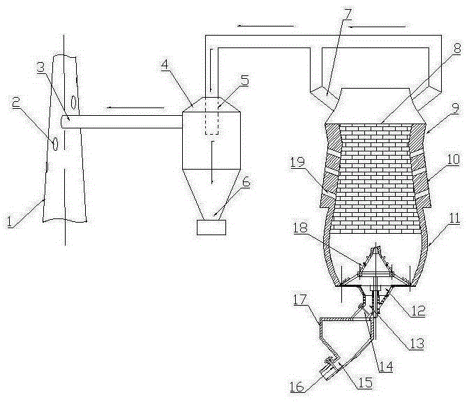
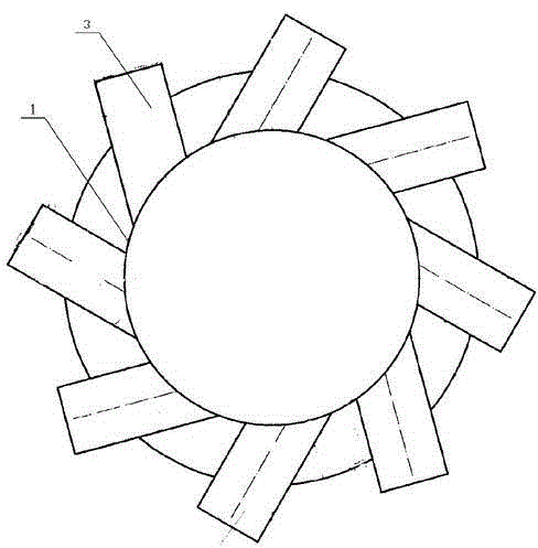
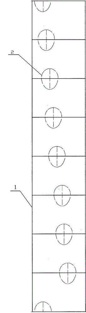
[0022] refer to Figure 1-3 , a nickel ore sintering machine, including several vertical kilns and a chimney 1 for concentrated discharge of exhaust gas, and a dust removal cylinder 4 is arranged between each vertical kiln and the chimney 1;

[0023] The vertical kiln comprises a kiln body consisting of an upper kiln body 9, a middle kiln body 10 and a lower kiln body 11. The top of the upper kiln body 9 is provided with a feeding port 8 and an exhaust gas discharge port 7, and the bottom of the lower kiln body 11 is provided with There is a discharge port 12, and a central tower grate 18 is installed at the discharge port 12. The lower section of the kiln body 11 opposite to the central tower grate 18 is set to expand outward ...


PUM


Abstract

The invention discloses a nickel ore sintering machine comprising a plurality of vertical kilns and a smoke pipe for concentrated discharge of tail gas, wherein a dust removal cylinder is arranged between each vertical kiln and the smoke pipe; each vertical kiln comprises a kiln body composed of an upper section kiln body, a middle section kiln body and a lower section kiln body; a feed port and a tail gas discharge port are formed in the top part of the upper section kiln body; a center tower gate is arranged at a discharge port of the lower section kiln body; the lower section kiln body relative to the center tower gate is set as an arc-shaped kiln body which is formed by expanding the middle part outwards and can guide side wind in a furnace to converge to the center of the furnace; a side air inlet is formed in the middle section kiln body; and a plurality of air inlets are formed in the wall of the smoke pipe, and different air inlets are formed in different cross sections of the smoke pipe. By forming the plurality of the air inlets, the nickel ore sintering machine disclosed by the invention improves the tail gas discharge amount of a unit time and improves the discharging efficiency; and by virtue of the arc-shaped kiln body, the wind is delivered to center tower gate and the center of an internal furnace combustion zone, and thus the nickel ore sintering efficiency is improved.

Description

technical field [0001] The invention relates to a nickel ore processing equipment, in particular to a nickel ore sintering machine. Background technique [0002] At present, the shaft kiln used in my country's cement industry is in the form of a single-tower grate ring discharge, and the kiln body of the shaft kiln is straight. "Excess, so that the coal in the ball is burned unevenly, resulting in a large loss of heat energy, low clinker quality, reduced output, and reduced labor production efficiency, and the tower grate of the large-diameter shaft kiln is bulky, making it difficult to manufacture and install , the normal firing and unloading of the clinker in the kiln cannot be guaranteed, the fixed jaw plate wears quickly, the replacement cycle is short, the discharge particle size is large, and the discharge temperature is high, which further increases the heat loss; secondly, in the nickel ore production process The exhaust gas produced passes through the two exhaust pipe...

Claims


Application Information

Patent Timeline
Patent Type & Authority Applications(China)
IPC IPC(8): C22B1/16
Inventor 相庆柱王世平
Owner 连云港泓聚莱釉料有限公司
Why Eureka
Try Eureka