Three-axis turntable device in the vacuum coating chamber

A technology of vacuum coating and pedestal transfer, which is applied in vacuum evaporation coating, sputtering coating, ion implantation coating, etc. It can solve the problem of low coating efficiency, high production cost, and inability to ensure that the target is facing each string of samples, etc. problem, to achieve the effect of simple structural design, increased furnace capacity, and avoiding vibration

Active Publication Date: 2017-07-21
NINGBO INST OF MATERIALS TECH & ENG CHINESE ACADEMY OF SCI
View PDF4 Cites 0 Cited by
  • Summary
  • Abstract
  • Description
  • Claims
  • Application Information

AI Technical Summary

Problems solved by technology

Among them, the most widely used one is that the targets are distributed around the cavity. This method is the most convenient to replace the targets, but it cannot guarantee that the targets are facing each string of samples under normal circumstances, and the substrates far away from the targets and facing away from the targets can only thin film
[0003] In order to solve the above problems, it is necessary to rely on the rotation of the substrate itself. At present, the most commonly used method is a two-axis rotation method that combines revolution and rotation. However, this method has low coating efficiency and high production costs.

Method used


Image

  • Three-axis turntable device in the vacuum coating chamber
  • Three-axis turntable device in the vacuum coating chamber

Examples


Embodiment 1

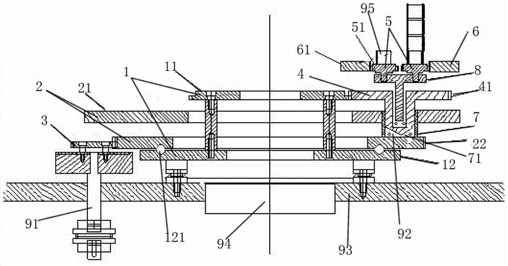
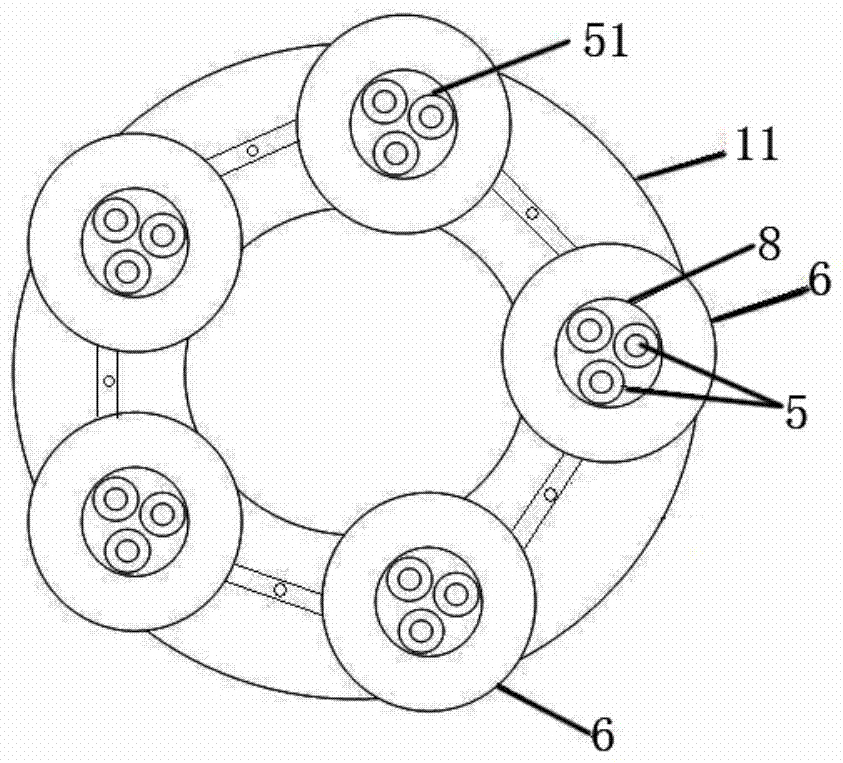
[0025] Please refer to figure 1 and figure 2 , the first gear set 1 is composed of the first upper gear 11 and the first lower gear 12, which are rigidly fixed by connecting arms to realize synchronous movement, the first lower gear 12 is fixed on the bottom plate 93 of the cavity, and its upper surface is engraved There is an annular groove 121 in which balls are placed. The second gear set 2 comprises a second upper gear 21 and a second lower gear 22, the lower surface of the second lower gear 22 is engraved with an annular groove 121 having the same diameter as the upper surface of the first lower gear 12, and the above two grooves 121 The second lower gear 22 can be placed on the first lower gear 12 by coincidence with the balls. There are five sleeve placement holes 71 evenly distributed on the upper surface of the second upper gear 21. The placement holes 71 and the second lower gear 22 A sleeve 7 as the first transmission part is fixed between them, and the second up...

Embodiment 2

[0028] The difference between this embodiment and the above-mentioned embodiment is that: the upper surface of the second upper gear 21 is evenly distributed with 8 placement holes 71, and the surface of the disc 8 is evenly distributed with 5 solid holes, and the furnace loading capacity is 40 strings, and the two-axis rotary base Compared with the 8-string furnace loading capacity of the rack, it has increased by 5 times.

Embodiment 3

[0030] The difference between this embodiment and the above-mentioned embodiment is that: there are 3 placement holes evenly distributed on the upper surface of the second upper gear 21, 4 solid holes are evenly distributed on the surface of the disc 8, and the furnace loading capacity is 12 strings, and the two-axis rotary base frame Compared with the 3-string furnace, the amount of furnace loading has increased by 4 times.

[0031] The motion principle and process created by the present invention are: when the motor 92 controls the rotation of the third gear 3, the third gear 3 drives the second lower gear 21 circumscribed therewith to rotate around the central axis 94 of the cavity. The second lower gear 22 is rigidly connected by the sleeve 7, so the fourth gear 41, disc 8, fifth gear 51, and sixth gear 61 placed in the sleeve 7 all surround the cavity with the second lower gear 22 The central axis 94 rotates, and since the sample to be coated 95 is fixed on the fifth gear...


PUM


Abstract

The invention discloses a three-axis rotary base frame device in a vacuum coating chamber, which comprises a first gear set, a second gear set, at least one first transmission member, a third gear, a fourth gear set, at least one second The transmission member, the fifth gear set, and the sixth gear set; the first gear set includes the first upper gear and the first lower gear, and these two gears are fixed together and rotate together, wherein the first lower gear is fixed in the cavity On the bottom plate; the second gear set includes a second upper gear, a second lower gear, and the second upper gear has a hole for placing the first transmission member, and the second upper gear is connected to the second lower gear through the first transmission member, wherein the second upper gear The bottom surface of the second lower gear is in sliding connection with the top surface of the first lower gear. The invention can solve the problem of how to maintain the three-axis rotation of the product so as to solve the phenomenon that samples are shielded from each other during the coating process, thereby ensuring the uniformity of the coating film on each surface of the sample.

Description

technical field [0001] The invention relates to a three-axis rotary base frame device placed in a vacuum coating chamber in a vacuum coating process, which is composed of several gears, and the sample to be coated can be simultaneously rotated around three axes by using only one motor. Rotate to solve the phenomenon that the samples are shielded from each other during the coating process, thereby ensuring the uniformity of the coating on each surface of the sample. Background technique [0002] Vacuum plating refers to the process of depositing various metal and non-metal films on the surface of products by evaporation, sputtering or ionization under vacuum conditions. It mainly includes vacuum evaporation, sputtering and ion plating. The product that needs to be coated is called the substrate, and the material to be plated is called the target; the substrate is fixed in the vacuum chamber through the base frame, and the target is usually located around, at the center, at th...

Claims


Application Information

Patent Timeline
Patent Type & Authority Patents(China)
IPC IPC(8): C23C14/50
Inventor 张栋汪爱英陈仁德许辉柯培玲
Owner NINGBO INST OF MATERIALS TECH & ENG CHINESE ACADEMY OF SCI
Why Eureka
Try Eureka