Material-fluid separation pulping equipment using airflow eddy kinetic energy

A technology of airflow vortex and kinetic energy, applied in the direction of raw material separation, fiber raw material, fiber raw material processing, etc., can solve the problems of high energy consumption and low efficiency, and achieve the effect of increasing crushing force, preventing clogging and maintaining stability

Inactive Publication Date: 2015-08-05
UNIV OF JINAN
View PDF6 Cites 4 Cited by
  • Summary
  • Abstract
  • Description
  • Claims
  • Application Information

AI Technical Summary

Problems solved by technology

[0004] Aiming at the problems of low efficiency and high energy consumption in the existing pulping equipment, the present invention provides a kind of air flow vortex kinetic energy pulping equipment which can effectively solve the above problems.

Method used


Image

  • Material-fluid separation pulping equipment using airflow eddy kinetic energy
  • Material-fluid separation pulping equipment using airflow eddy kinetic energy
  • Material-fluid separation pulping equipment using airflow eddy kinetic energy

Examples


Embodiment

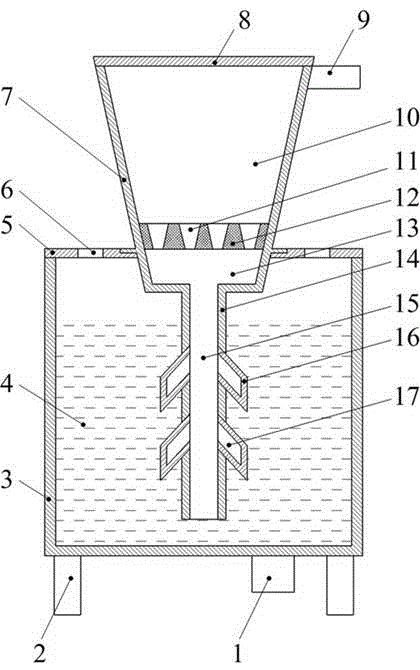
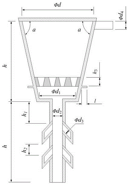
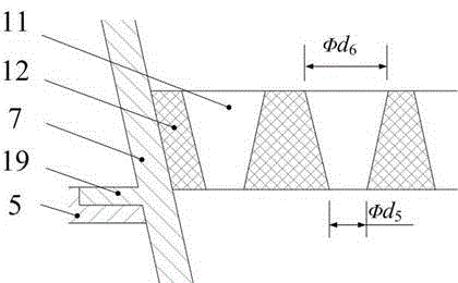
[0028] Such as figure 1 As shown, an air vortex kinetic energy pulping equipment for material-liquid separation in the present invention mainly includes an air vortex crushing device and a slurry generating device. The airflow vortex crushing device is mainly composed of an air inlet pipe 9, a material cylinder cover 8, a material cone 7, a material filter device 11, a material conveying main pipe 14 and a material conveying branch pipe 16, and the air inlet pipe 9 is installed on the material cone. At the outer edge of the upper end of 7, the material barrel cover 8 is installed on the material cone 7, and the crushed material filter device 11 is installed at the lower end of the material cone 7, and the material tank cover 8, the material cone 7 and the crushed material filter device 11 form a vortex In the crushing area 10, the bottom end of the material cone 7 is designed with a crushed material conveying main pipe 14, and the crushed material conveying main pipe 14 is de...


PUM


Abstract

The invention discloses material-fluid separation pulping equipment using airflow eddy kinetic energy. The material-fluid separation pulping equipment mainly comprises an airflow eddy crushing device and a pulp generation device. The material-fluid separation pulping equipment is characterized in that the material-liquid separation includes that using airflow eddy kinetic energy to crush the material and mixing with liquid water to generate size. The material-fluid separation pulping equipment realizes the minimum energy-loss gas circulation through a gas inlet pipeline tangential to the edge of the outer side of the upper end of a conical material cylinder, realizes acceleration rotational flow and increases the airflow eddy crushing force through the conical material cylinder, realizes the crushed material sieving through a crushed material filtering device and realizes to quickly mix and stir to generate uniform pulp through a main crushed material conveying pipe, a branch crushed material conveying pipe and a liquid barrel.

Description

technical field [0001] The present invention relates to an air flow vortex kinetic energy pulping equipment for separation of material and liquid, in particular to a gas circulation with minimum energy loss realized through an air inlet pipe tangent to the outer edge of the upper end of the material cone, and accelerated vortex through the material cone. Flow and increase the vortex crushing force of the airflow, realize the screening of the crushed material through the crushed material filter device, realize the rapid mixing of liquid water and the crushed material through the crushed material conveying main pipe, the crushed material conveying branch pipe and the liquid cylinder, and generate a uniform slurry, which belongs to papermaking The field of technology research and development of industrial pulping equipment. Background technique [0002] The generation of pulp in the paper industry requires pulping equipment, such as the most commonly used hydraulic pulper, whic...

Claims


Application Information

Patent Timeline
Patent Type & Authority Applications(China)
IPC IPC(8): D21B1/34
CPCD21B1/34D21B1/345
Inventor 安延涛赵东刘鲁宁杨玉娥
Owner UNIV OF JINAN
Why Eureka
Try Eureka