Supercharge Your Innovation With Domain-Expert AI Agents!

Electric parking brake device

A brake device, electric technology, applied in the direction of transmission device, electric device, electromagnetic measuring device, etc., can solve the problem of loss and other problems, achieve the effect of reducing cost, realizing size and avoiding accidents

Inactive Publication Date: 2015-08-05
NTN CORP
View PDF6 Cites 8 Cited by
  • Summary
  • Abstract
  • Description
  • Claims
  • Application Information

AI Technical Summary

Problems solved by technology

[0026] In addition, the voltage source that supplies the AC voltage must output an AC voltage with an amplitude and frequency suitable for detection, so there is also a problem of loss due to conversion.
In particular, in the case of a vehicle, it is driven by a battery, so there is a problem of trying to reduce the above-mentioned loss
[0027] In addition, if a loss occurs in this way, a heat sink must be provided to dissipate the loss, and a space for mounting a circuit of an AC voltage source is also required.

Method used


Image

  • Electric parking brake device
  • Electric parking brake device
  • Electric parking brake device

Examples


Embodiment 1

[0112] The first embodiment relates to temperature rise of the solenoid 9 in addition to the above-mentioned operation and effect, and describes how the accuracy of estimating the position and displacement of the plunger 10 can be improved by compensating for a decrease in the magnetic field caused by the temperature rise.

[0113] That is, the solenoid 9 uses a copper wire for the coil 37 . At this copper wire there is a DC resistance which has a positive temperature coefficient. Therefore, when the DC resistance of the coil 37 increases due to an increase in temperature (including ambient temperature), the excitation current decreases, and the magnetomotive force decreases.

[0114] here, in Figure 6 Since a current control circuit is used for driving the solenoid 9, control is performed so that a constant current is supplied even if the temperature changes.

[0115] However, in general, when normalizing the relationship between the DC resistance and the temperature coeff...

Embodiment 2

[0129] In this second embodiment, in addition to the above-mentioned operation and effect, the state of the parking brake device is periodically confirmed (inspected) to improve safety.

[0130] That is, the position of the plunger 10 of the solenoid 9 is estimated and confirmed when the parking brake device is OFF and when the parking brake device is operating.

[0131] The case where the parking brake device is disconnected refers to the case where the brake pedal is operated to actuate the main brake (foot brake). 42 is separated and confirmed, so that there is no hindrance to the action of the main brake. Therefore, this confirmation is always performed by sequentially estimating the position of the plunger 10 of the solenoid 9 every predetermined period of time shorter than the operation period of the solenoid 9 using the methods of the embodiment and Example 1. FIG. Accordingly, malfunction of the plunger 10 can be detected.

[0132] In this way, if Figure 6 As shown, ...

Embodiment 3

[0138] The third embodiment is used to compensate for the estimation of the position of the plunger 10 when a lateral force is applied to the vehicle body, that is, a parallel force is applied to the axle connecting the left and right wheels, in addition to the above-mentioned effects.

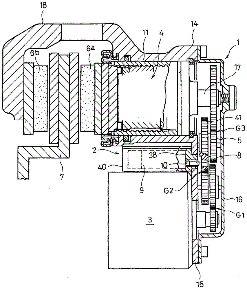
[0139] In this case, if figure 1 As shown, the plunger 10 of the solenoid 9 is perpendicular to the axle-mounted brake disc 7 and is arranged parallel to the axle. Therefore, when a lateral force is applied with respect to the vehicle body, a force in the advancing and retreating direction is applied to the plunger 10 , which may cause an error in the estimated position.

[0140] In order to solve the above problems, such as Figure 6 As shown, the vehicle is provided with an acceleration sensor 61 for detecting lateral acceleration. Then, when the lateral acceleration detected by the sensor 61 is detected to be a value greater than a certain value, in other words, when the plunger 10 reache...


PUM


Abstract

In this electric parking brake device, electrical power loss is low when detecting the displacement or position of a plunger without providing a sensor, and the mounting space is also caused to be low. A resonance capacitor (54) is connected to the coil (37) of a solenoid (9), forming a resonance circuit, and a drive current to which is superposed a resonance frequency is input to the solenoid (9) forming the resonance circuit. As a result, when the position of the plunger (10) within the coil (37) changes, the inductance of the coil (37) changes, and the resonance frequency moves. From said change, the position or displacement of the plunger (10) is detected without providing a sensor, and so the installation space thereof is not required. In such a manner, a resonance output is superposed and the changes in detection value (changes in resonance point) of both ends of the solenoid (9) are detected, and so a large electrical power is not required and losses are low.

Description

technical field [0001] The present invention relates to an electric parking brake device using an electric brake. Background technique [0002] As an electric parking device using an electric brake, there is an electric disc brake device disclosed in Patent Document 1. [0003] This brake device proposes a parking brake mechanism for an automobile using a solenoid. [0004] Next, since the mechanical part of the brake device has substantially the same structure as that of the electric parking brake device of the present application, a formula representing an embodiment of the present application is used. figure 1 Be explained. [0005] Such as figure 1 As shown, the braking device is composed of an electric brake 1 and a parking unit 2 . [0006] The electric brake 1 has a structure in which an electric motor 3 and a direct-acting mechanism 4 are connected via a speed reduction mechanism 5 , and brake pads 6 a attached to the direct-acting mechanism 4 are pressed against...

Claims


Application Information

Patent Timeline
Patent Type & Authority Applications(China)
IPC IPC(8): F16D65/18F16H35/00G01B7/00H01F7/18F16D121/24F16D125/40F16D125/48F16D127/06F16D129/08
CPCF16D2127/06F16D2125/40H01F7/18F16D2125/48F16D55/226F16D63/006B60T13/741F16D2129/08B60T1/005G01B7/003G01B7/00F16D2121/24F16D65/18F16D2125/50
Inventor 增田唯西川明良
Owner NTN CORP
Features
  • R&D
  • Intellectual Property
  • Life Sciences
  • Materials
  • Tech Scout
  • Unparalleled Data Quality
  • Higher Quality Content
  • 60% Fewer Hallucinations
Learn More