Camshaft axial limit structure

A technology of axial limit and camshaft, which is applied in the direction of engine components, machines/engines, mechanical equipment, etc., can solve the problems of reducing the overall body stability and body vibration

Active Publication Date: 2017-08-04
遵义市文杰机电有限责任公司
View PDF5 Cites 0 Cited by
  • Summary
  • Abstract
  • Description
  • Claims
  • Application Information

AI Technical Summary

Problems solved by technology

[0005] The technical problem to be solved by the present invention is that the axial limit of the current camshaft is rigid, causing the vibration of the camshaft to be transmitted to the body, and when the thrust plate or the thrust screw limits the camshaft, The body is impacted by the camshaft, causing the body to vibrate and reducing the stability of the whole body

Method used


Image

  • Camshaft axial limit structure
  • Camshaft axial limit structure

Examples


Embodiment Construction

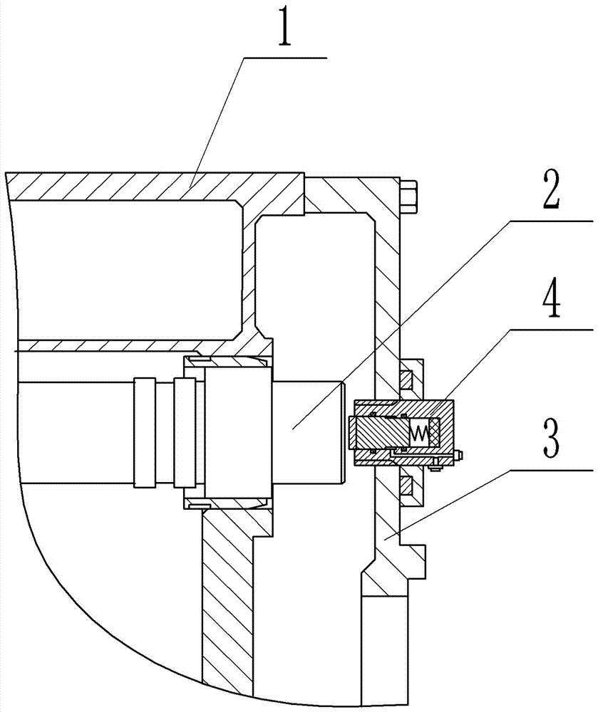
[0017] Such as figure 1 As shown, the camshaft axial limit structure of the present invention includes a body 1, a camshaft 2 and an end cover 3, the camshaft 2 is installed on the body 1, and the end cover 3 is bolted to the body 1; the end cover 3 is located on the camshaft 2 The limit seat 4 is installed at the corresponding position of the end face, and the limit seat 4 and the end cover 3 are connected by threads.

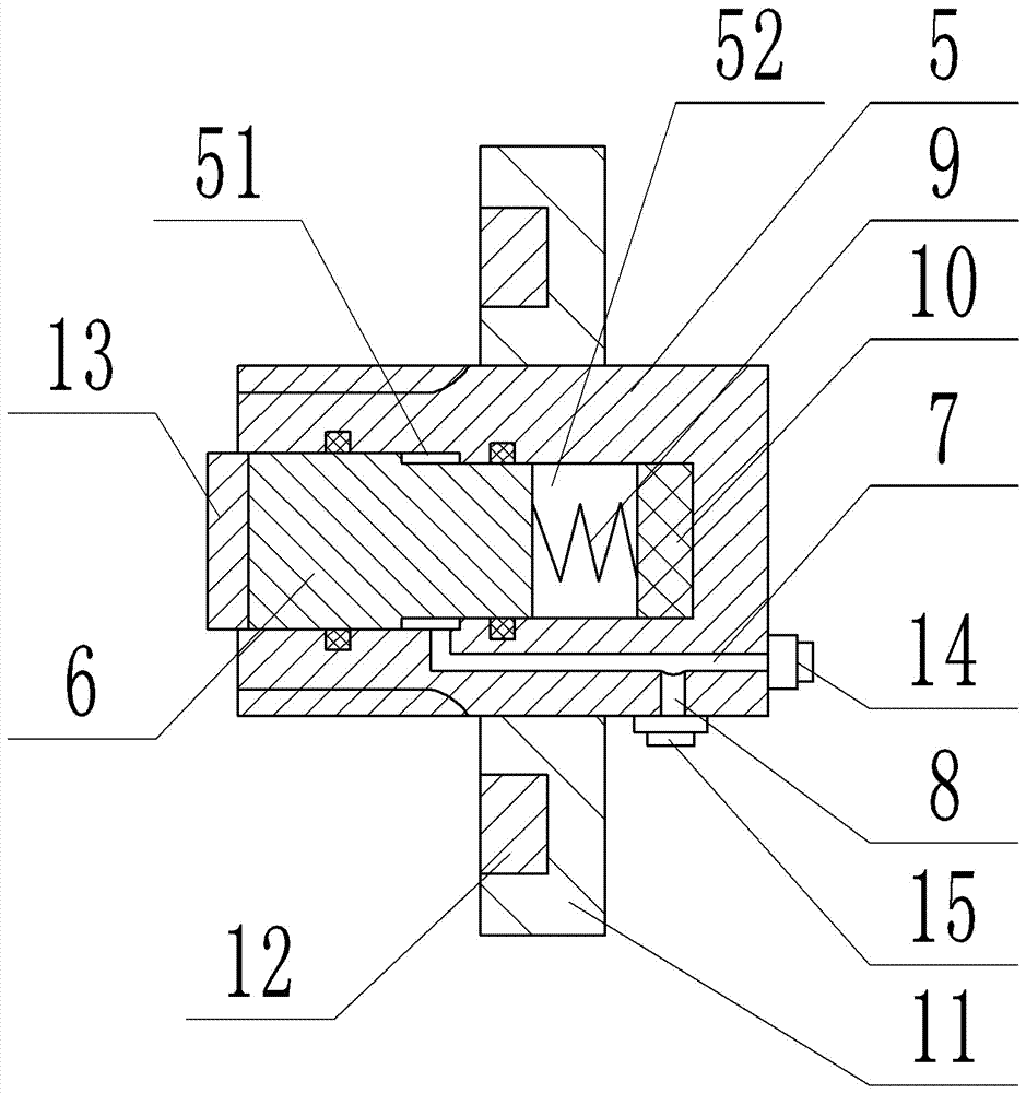
[0018] Such as figure 2 As shown, the limit seat 4 includes a hydraulic cylinder barrel 5 and a limit column 6, and the hydraulic cylinder barrel 5 is provided with a first chamber 51, a second chamber 52, a main oil circuit 7 and a branch oil circuit 8. A chamber 51 communicates with the second chamber 52, the aperture of the first chamber 51 is 2 cm larger than the aperture of the second chamber 52, and the axis line of the first chamber 51 is the same as that of the second chamber 52. line, the main oil circuit 7 communicates with the first chamber 51, t...


PUM


Abstract

The invention relates to an axial limiting structure for a cam shaft. The axial limiting structure for the cam shaft overcomes the defect that the axial limiting of an existing cam shaft is rigid limiting, so that shaking of the cam shaft is transmitted to a machine body, and an impact force subjected by the machine body from the cam shaft leads the machine body to shake when a thrust plate or a thrust bolt conducts liming on the cam shaft. The provided axial limiting structure for the cam shaft comprises a machine body, the cam shaft and an end cover. A position, corresponding to the end face of the cam shaft, on the end cover is provided with a limiting seat. The limiting seat comprises a hydraulic cylinder barrel and a limiting column. The hydraulic cylinder barrel is provided with a first cavity, a second cavity, a main oil circuit and a branch oil circuit. The bore diameter of the first cavity is greater than that of the second cavity. The main oil circuit is communicated with the first cavity. The branch oil circuit is communicated with the main oil circuit. A liquid inlet valve is arranged at an outlet of the main oil circuit. A safe valve is arranged at an outlet of the branch oil circuit. The limiting column comprises a first piston part and a second piston part from left to right. The end portion of the second piston part is provided with an elastic component. The bottom of the second cavity is provided with a shock absorption component.

Description

technical field [0001] The invention belongs to the field of power devices, and in particular relates to a camshaft axial limit structure. Background technique [0002] The camshaft is an important part in a piston engine, and its function is to control the opening and closing of the valves. Although the speed of the camshaft in a four-stroke engine is half that of the crankshaft (the speed of the camshaft is the same as that of the crankshaft in a two-stroke engine), it is usually still high in speed and needs to withstand a lot of torque, so the design of The camshaft has high requirements on strength and support, and its material is generally high-quality alloy steel or alloy steel. [0003] In the traditional engine camshaft connection structure, in order to prevent the axial movement of the camshaft, the camshaft should be axially positioned. If the axial clearance is too small, the machine parts will be damaged, if the axial clearance is too large, it will affect the...

Claims


Application Information

Patent Timeline
Patent Type & Authority Patents(China)
IPC IPC(8): F01L1/46F01L1/047
CPCF01L1/047F01L1/46F01L2810/03
Inventor 杨盛强
Owner 遵义市文杰机电有限责任公司
Why Eureka
Try Eureka