A Gas/Dual Fuel Engine Gas Ladder Injection Device

A dual-fuel engine and injection device technology, which is applied to fuel injection devices, combustion engines, machines/engines, etc., can solve problems such as combustion stability and NOx emission performance are not ideal, to achieve the expansion of lean burn limit, improve combustion quality, The effect of speeding up the mixing

Active Publication Date: 2017-03-01
HARBIN ENG UNIV
View PDF9 Cites 0 Cited by
  • Summary
  • Abstract
  • Description
  • Claims
  • Application Information

AI Technical Summary

Problems solved by technology

However, this gas injection structure easily leads to an increase in the randomness of the gas and air concentration distribution in the cylinder. When the engine is working under certain operating conditions, especially in lean-burn conditions, the concentration gradient in the cylinder is too large, resulting in combustion stability. and NOx emission performance is not ideal

Method used


Image

  • A Gas/Dual Fuel Engine Gas Ladder Injection Device
  • A Gas/Dual Fuel Engine Gas Ladder Injection Device
  • A Gas/Dual Fuel Engine Gas Ladder Injection Device

Examples


Embodiment example 1

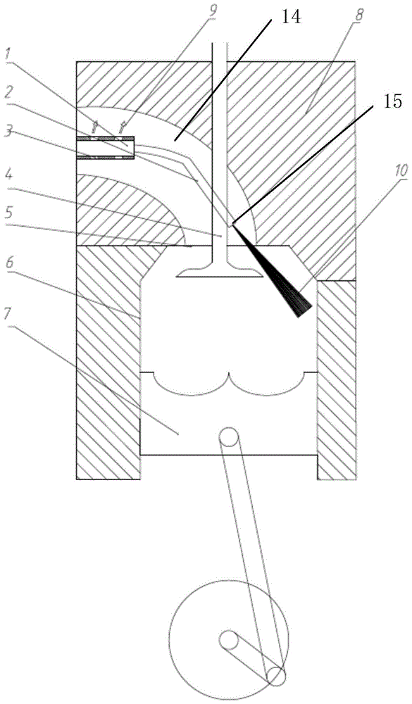
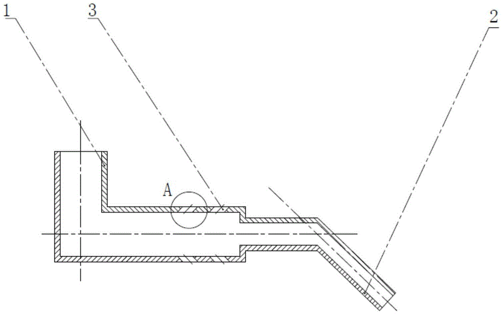
[0020] Implementation Case 1: Combining Figure 1 to Figure 7 , the present invention includes a cylinder head 8 and a cylinder body 6, the cylinder head 8 is provided with a manifold pipe 14, and a large-flow gas nozzle is also installed on the manifold pipe 14, and the large-flow gas nozzle includes an upper half Nozzle 1 and the lower half nozzle 2 fixedly connected with the upper half nozzle 1, the lower half nozzle 2 is an elbow, and the end of the lower half nozzle 2 is provided with a lower half air outlet 15, the gas passes through the lower half The first half of the air outlet 15 is sprayed into the cylinder main body 6 to form a gas pulse 10. The outer surface of the upper half of the nozzle 1 is provided with an upper half of the air outlet 3. The arrangement of the upper half of the air outlet 3 is: along the At least two air outlet groups are arranged in the length direction of the upper half nozzle, and each air hole group has at least four upper half air outlet...

Embodiment example 2

[0024] Embodiment 2: Based on the above embodiment, the present invention can also be: the diameter of the lower nozzle 2 is smaller than the diameter of the upper nozzle 1 , that is, the diameter of the lower nozzle 2 is smaller than that of the upper nozzle 1 .

Embodiment example 3

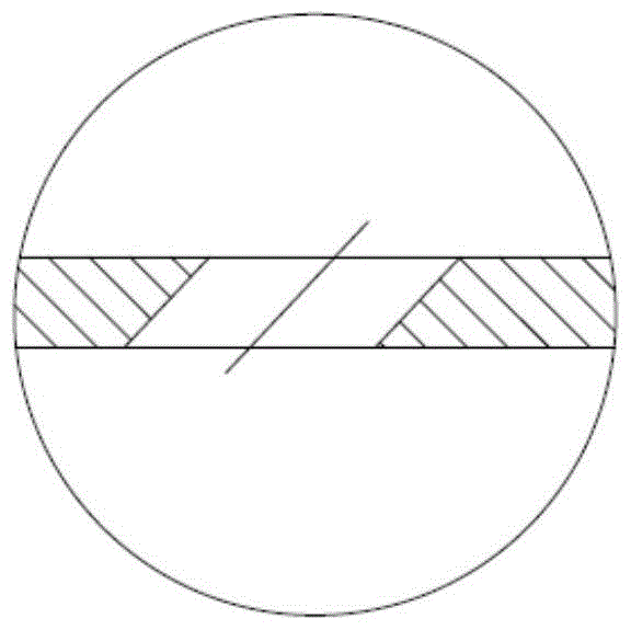
[0025] Embodiment 3: Based on the above-mentioned embodiment and in combination with Fig. 3(A) and Fig. 3(B), the present invention can also be: the clamp between the axis of the upper half of the air outlet 3 and the axis of the upper half of the nozzle 1 The angle is 90° or 45° or 135°. The air outlet 3 of the upper half is a through hole with a diameter of 1-3 mm, connecting the inner cavity of the upper nozzle 1 and the air inlet, and the axis of the upper air outlet 3 of the upper half and the air flow direction of the air inlet At a certain angle, there are currently three design schemes, (1) the axis of the air outlet 3 in the upper half of the upper half is 45° to the axis of the nozzle 1 in the upper half, and the ejected gas pulse 9 is consistent with the incoming flow direction of the intake air; (2) ) The axis of the air outlet 3 in the upper half of the upper half is 135° to the axis of the nozzle 1 in the upper half, and the ejected gas pulse 9 is opposite to the...


PUM


Abstract

The invention provides a gas / dual-fuel engine fuel gas echelon spraying device, which comprises an air cylinder cover and an air cylinder main body, wherein a manifold pipeline is arranged on the air cylinder cover; a high-flow-rate fuel gas spray nozzle is also arranged on the manifold pipeline and comprises a spray nozzle upper half section and a spray nozzle lower half section fixedly connected with the spray nozzle upper half section; the spray nozzle lower half section is a bent pipe; in addition, the tail end of the spray nozzle lower half section is provided with a lower half section air outlet hole; upper half section air outlet holes are formed in the outer surface of the spray nozzle upper half section; the upper half section air outlet holes are arranged in a way that at least two lines of air outlet hole groups are arranged along the length direction of the upper half section spray nozzle, each line of air outlet hole group at least comprises four upper half section air outlet holes, in addition, each line of upper half section air outlet holes are uniformly distributed along the circumferential direction of the upper half section spray nozzle, and the hole diameter of each upper half section air outlet hole is smaller than the hole diameter of the lower half section air outlet holes. The gas / dual-fuel engine fuel gas echelon spraying device has the advantages that the mixing and layering requirements of the fuel gas and the air can be met, the engine combustion process is optimized, and the economic performance and the emission performance are improved.

Description

technical field [0001] The invention relates to an injection device, in particular to a gas ladder injection device for a gas / dual-fuel engine, and belongs to the technical field of engines. Background technique [0002] With the increasingly serious energy crisis and environmental pollution, various energy-saving and emission-reduction technologies are being actively developed at home and abroad. Natural gas has become a new generation of alternative energy due to its high calorific value, clean combustion and abundant reserves. Among them, lean combustion can effectively reduce NOx emissions due to its low combustion temperature, and has become an important emission reduction technology. However, as the mixture becomes leaner, the cycle variation of the engine will intensify, and even when the engine is running near the lean limit, partial combustion or misfire will occur, and the HC and CO in the exhaust gas will increase significantly, and the cycle change will become a...

Claims


Application Information

Patent Timeline
Patent Type & Authority Patents(China)
IPC IPC(8): F02M21/02F02M51/06F02M61/14
CPCY02T10/30
Inventor 杨立平李越宋恩哲马修真姚崇石勇杨晓涛
Owner HARBIN ENG UNIV
Why Eureka
Try Eureka