Liquid nitrogen cooling tower solar thermoelectric power station

A tower type solar energy and liquid nitrogen cooling technology, applied in the field of solar power generation, can solve the problems of insufficient temperature difference, low heat exchange efficiency, insufficient utilization efficiency of concentrated high-temperature heat energy, etc. The effect of utilization efficiency

Inactive Publication Date: 2015-08-12
上海领势新能源科技有限公司 +1
View PDF10 Cites 1 Cited by
  • Summary
  • Abstract
  • Description
  • Claims
  • Application Information

AI Technical Summary

Problems solved by technology

However, this solar power generation method is cooled by air, and the heat exchange efficiency is low; at the same time, the temperature of the air is still relatively high, and the temperature difference between the high temperature generated by the concentrated light is not large enough. According to the Carnot cycle efficiency law, the heat generated by the concentrated light The utilization efficiency of high temperature heat energy is not high enough

Method used


Image

  • Liquid nitrogen cooling tower solar thermoelectric power station

Examples


Embodiment 1

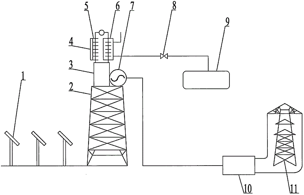
[0017] Embodiment one: see figure 1 , a liquid nitrogen cooling tower solar thermal power station, comprising a tower, a reflector field, a heat absorber, a generator, a thermoelectric engine, and a liquid nitrogen storage tank.

[0018] The cooler of the program-controlled switch-type thermoelectric engine is enclosed in a sealed box, and the box has at least one inlet for liquid nitrogen to enter, and at least one outlet for nitrogen to discharge.

[0019] As the cooling medium, liquid nitrogen flows out from the liquid nitrogen storage tank, enters the sealed box where the cooler of the thermoelectric engine is located in a liquid state, cools the cooler of the thermoelectric engine, and is vaporized into gas, which is discharged into the atmosphere from the outlet.

[0020] Between the liquid nitrogen storage tank and the sealed box where the cooler is located, a throttle valve is installed to adjust the flow of liquid nitrogen, and the throttle valve is controlled by the ...


PUM


Abstract

A liquid nitrogen cooling tower solar thermoelectric power station comprises a tower truss, a mirror field, a heat absorber, a generator, a thermoelectric engine, and a liquid nitrogen storage tank. A cooler of the program-controlled switching thermoelectric engine is sealed in a sealed box which has at least one inlet for feeding liquid nitrogen and at least one outlet for discharging liquid nitrogen. Liquid nitrogen as a cooling medium flows out of the liquid nitrogen storage tank, enters the sealed box where the cooler of the thermoelectric engine is disposed in the form of liquid to cool the cooler of the thermoelectric engine, and is then gasified and discharged into atmosphere from the outlet. According to the invention, the thermoelectric engine is cooled with liquid nitrogen, which is higher in efficiency than a mode of cooling with air. The efficiency of solar energy conversion can be greatly improved. A method for obtaining higher solar generation power per unit area is provided. The liquid nitrogen cooling tower solar thermoelectric power station is applicable to occasions having high requirement on power and a limited space.

Description

technical field [0001] The present invention relates to the technical field of solar power generation, in particular to a tower-type solar thermal power station (see patent application number 201410771206.4), and an energy storage tower-type solar thermal power station (see patent application number 201510030003.4). It also relates to a program-controlled switch type thermoelectric engine (see patent application number 201410058639.5), a multi-cylinder thermoelectric engine (see patent application number 201410712134.6), a rotor type thermoelectric engine (see patent application number 201410679583.5), a positive A temperature difference engine controlled by a time system (see patent application number 201410740508.5). Background technique [0002] Recently, a technical solution called a tower-type solar thermal power station (see patent application number 201410771206.4) was proposed. This kind of solar thermoelectric power generation device takes the thermoelectric engine...

Claims


Application Information

Patent Timeline
Patent Type & Authority Applications(China)
IPC IPC(8): F03G6/00F25D3/10
CPCF03G6/00F03G6/06F25D3/10F03G6/063Y02E10/46
Inventor 虞一扬
Owner 上海领势新能源科技有限公司
Why Eureka
Try Eureka