AI technical title is built by Patsnap AI team. It summarizes the technical point description of the patent document.
A flotation column, a new type of technology, applied in flotation, solid separation, etc., can solve problems such as back-mixing, entrainment, unfavorable sorting, etc., and achieve the effect of preventing back-mixing and improving sorting efficiency
Inactive Publication Date: 2015-08-19
WUHAN INSTITUTE OF TECHNOLOGY
View PDF8 Cites 10 Cited by
Summary
Abstract
Description
Claims
Application Information
AI Technical Summary
This helps you quickly interpret patents by identifying the three key elements:
Problems solved by technology
Method used
Benefits of technology
Problems solved by technology
Existing flotation columns, such as "a static microbubble flotation column enhanced separation method and device" disclosed in patent 97107091.1, "one type of static flotation column" disclosed in patent 98225790.2, "one type of static flotation column" disclosed in patent 99232178.6 Static micro-bubble flotation column", "an improved swirling static micro-bubble flotation column" disclosed in patent 200502128590.2, "a swirling static micro-bubble flotation column" disclosed in patent 200810143584.2, etc., all use rising air bubbles Mineralization by colliding with the pulp inside the column, the concentrate is discharged from the top of the flotation column, and the tailings are discharged from the bottom of the flotation column. The above-mentioned flotation column has the following disadvantages: 1) The countercurrent contact between the rising bubbles and the descending pulp is not sufficient, which is not conducive to Separation; 2) The bottom of the flotation column is easy to silt and block; 3) The pulp is easy to form an unstable flow state in the flotation column, and the entrainment phenomenon is serious, which is not conducive to separation; 4) The thickness of the foam layer of the flotation column is not enough, and the tiny bubbles It is easy to merge and become larger and broken, resulting in serious back-mixing, which is not conducive to separation; 5) Once the scale of ore pulp processing is expanded, it is difficult for the traditional flotation column to achieve the ideal separation effect, and the tailings grade is difficult to meet the requirements
Method used
Image
Click on the blue label to locate the original text in one second.
Reading with bidirectional positioning of images and text.
Examples
Embodiment 1
[0028] Ore sample: Ore sample from a mining area in Yichang, raw ore P 2 o 5 The grade is 26.64%, and the MgO content is 4.6%.
[0029] Operation steps: first crush, grind and classify the raw phosphate ore, control the grindingfineness to -200 mesh > 80%, the concentration of the grindingslurry is 35%, the flotation temperature is about 25°C, and then introduce the slurry into the ore In the chemical tank, the pH value of the pulp is controlled to be 8.6, and the fatty acid collector 2.5kg / t is fully mixed with the pulp, and then the resulting mixture is introduced into the flotation column, and the pulp passes through one or more in the upper part of the flotation column. A feeding point enters the flotation column.
[0030] Test results: Phosphorus concentrate P after flotation 2 o 5 The grade is 31.64%, the MgO content is 0.92%, and the P2O5 recovery rate reaches 91.8%.
Embodiment 2
[0032] Ore sample: Ore sample from a mining area in Yichang, raw ore P 2 o 5 The grade is 26.84%, and the MgO content is 4.4%.
[0033] Operation steps: Crushing, grinding and classifying raw phosphate ore, controlling the grinding fineness to -200 mesh > 80%, the concentration of the grinding slurry at 30%, the flotation temperature at about 25°C, and adding fatty acid collectors 2.5kg / t, and the pH value of the pulp is controlled to be 8.2.
[0034] Test results: Phosphorus concentrate P after flotation 2 o 5 Grade 31.64%, MgO content 0.84%, P2 o 5 The recovery rate reached 90.8%.
Embodiment 3
[0036] Ore sample: Ore sample from a mining area in Yichang, raw ore P 2 o 5 Grade 27.3%, MgO content 4.8%.
[0037] Operation steps: Crushing, grinding and classifying raw phosphate ore, controlling the grinding fineness to -200 mesh > 80%, the concentration of the grinding slurry at 30%, the flotation temperature at about 25°C, and adding fatty acid collectors 2.7kg / t, and the pH value of the pulp is controlled to be 8.8.
[0038] Test results: Phosphorus concentrate P after flotation 2 o 5 Grade 32.57%, MgO content 0.83%, P 2 o 5 The recovery rate reached 92.6%.
PUM
Abstract
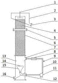
The invention relates to a novel flotation column. A main body of the novel flotation column is a column body; two-section type pore plate rolling padding is arranged in the column body; a middling circulating device is arranged on the lower portion of the column body and comprises an inverted-cone-shaped barrel, a circulating pump and an air bubble generator which are sequentially connected to one another through a pipe; the inverted-cone-shaped barrel is arranged in the column body; an opening of the inverted-cone-shaped barrel is upward; the circulating pump and the air bubble generator are arranged on the outside of the column body; the inverted-cone-shaped barrel is connected with the circulating pump through a liquid inlet pipe; and the air bubble generator is connected with the inside of the column body through a liquid outlet pipe. The novel flotation column is simple in structure and cannot be blocked easily; rising air bubbles are in contact with descending ore pulp sufficiently; and the flow state of the ore pulp is stable.
Description
technical field [0001] The invention relates to a novel flotation column. Background technique [0002] Flotation column is a common mineral flotation equipment. Existing flotation columns, such as "a static microbubble flotation column enhanced separation method and device" disclosed in patent 97107091.1, "one type of static flotation column" disclosed in patent 98225790.2, "one type of static flotation column" disclosed in patent 99232178.6 Static micro-bubble flotation column", "an improved swirling static micro-bubble flotation column" disclosed in patent 200502128590.2, "a swirling static micro-bubble flotation column" disclosed in patent 200810143584.2, etc., all use rising air bubbles Mineralization by colliding with the pulp inside the column, the concentrate is discharged from the top of the flotation column, and the tailings are discharged from the bottom of the flotation column. The above-mentioned flotation column has the following disadvantages: 1) The counterc...
Claims
Application Information
Patent Timeline
Application Date:The date an application was filed.
Publication Date:The date a patent or application was officially published.
First Publication Date:The earliest publication date of a patent with the same application number.
Issue Date:Publication date of the patent grant document.
PCT Entry Date:The Entry date of PCT National Phase.
Estimated Expiry Date:The statutory expiry date of a patent right according to the Patent Law, and it is the longest term of protection that the patent right can achieve without the termination of the patent right due to other reasons(Term extension factor has been taken into account ).
Invalid Date:Actual expiry date is based on effective date or publication date of legal transaction data of invalid patent.

