Check patentability & draft patents in minutes with Patsnap Eureka AI!

Detection method of laser processing groove

A technology of laser processing and detection method, which is applied in the direction of laser welding equipment, metal processing equipment, manufacturing tools, etc., can solve the problems of inspection, device influence, inability to play rough groove incision, etc., and achieve the effect of reducing the time spent

Active Publication Date: 2018-04-06
DISCO CORP
View PDF6 Cites 0 Cited by
  • Summary
  • Abstract
  • Description
  • Claims
  • Application Information

AI Technical Summary

Problems solved by technology

However, in this machining method, the edge of the thick groove covering the thin groove cannot be distinguished even when viewed from above, so the function of notch inspection (positional deviation correction) of the rough groove cannot be exerted during machining. In particular, The positional deviation of the coarse groove may have an impact on the device

Method used


Image

  • Detection method of laser processing groove
  • Detection method of laser processing groove
  • Detection method of laser processing groove

Examples


Embodiment approach

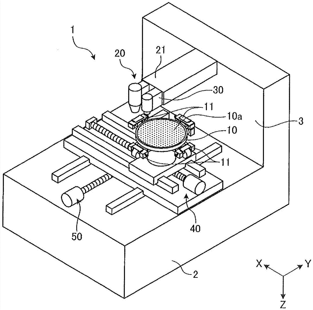
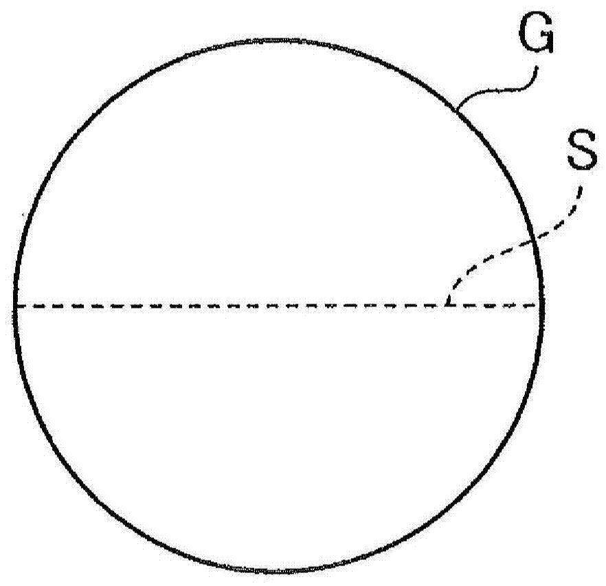
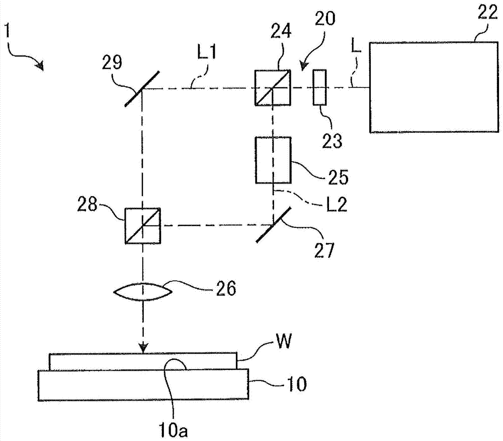
[0047] The detection method of the laser processing groove which concerns on embodiment of this invention is demonstrated based on drawing. figure 1 It is a perspective view which shows the structural example of the laser processing apparatus which concerns on the detection method of the laser processing groove which concerns on embodiment. figure 2 is showing figure 1 A diagram showing the image of the imaging member of the laser processing device. image 3 is showing figure 1 A diagram showing the structure of the laser beam irradiation member of the laser processing device shown. Figure 4is shown as figure 1 A perspective view of a wafer or the like to be processed by the laser processing apparatus shown.

[0048] The detection method (hereinafter, simply referred to as the detection method) of the laser processing groove of the embodiment is to use figure 1 The method performed by the laser processing apparatus 1 shown (that is, the method using the laser processing...


PUM


Abstract

The present invention provides a detection method for a laser processing groove, wherein the position shifting influence of a coarse groove on devices can be avoided. The detection method for the laser processing groove comprises the steps of a first groove checking step (ST1) and a second groove checking step (ST3). During the first groove checking step (ST1), a first groove is formed at a segmentation predetermined line by using a first laser light. Meanwhile, the first groove is shot by a shooting part, so that the position of the first groove can be detected. During the second groove checking step (ST3), a second groove is formed at a segmentation predetermined line within the remaining area by using a second laser light. Meanwhile, the second groove is shot by the shooting part, so that the position of the second groove can be detected. According to the detection method for the laser processing groove, the position shifting of the first groove and the position shifting of the second groove can be detected, so that the first groove and the second groove are positioned at specified locations.

Description

technical field [0001] The invention relates to a detection method for laser processing grooves. Background technique [0002] In dividing a wafer on which devices are formed by a Low-k film (low dielectric constant film), the following processing method is known: In order to cope with the fragility and peelability of the Low-k film, by irradiating laser light In the ablation process realized, two processing grooves for dividing the Low-k film are formed on both sides of the planned dividing line, and then the processing grooves are divided by a cutting tool (for example, refer to Patent Document 1). [0003] Patent Document 1: Japanese Patent Laid-Open No. 2005-64231 [0004] In the processing method shown in the aforementioned Patent Document 1, in order to prevent partial wear of the cutting tool that cuts along the processing grooves, in many cases, the interval between the outer edges of the processing grooves formed on both sides is formed. is the interval exceeding ...

Claims


Application Information

Patent Timeline
Patent Type & Authority Patents(China)
IPC IPC(8): H01L21/66B23K26/364B23K26/402B23K26/064B23K26/03
CPCH01L21/268H01L21/76H01L22/12H01L24/98H01L2221/68327
Inventor 法积大吾大久保广成
Owner DISCO CORP
Features
  • R&D
  • Intellectual Property
  • Life Sciences
  • Materials
  • Tech Scout
  • Unparalleled Data Quality
  • Higher Quality Content
  • 60% Fewer Hallucinations
Learn More