Novel hole drilling machine for processing plate materials and hole drilling method

A drilling machine and drilling mechanism technology, applied in wood processing equipment, drilling machines, manufacturing tools, etc., can solve the problems of high labor intensity of production personnel, large damage to the surface of the board, and affecting the quality of the board, so as to improve drilling efficiency, The effect of reducing labor intensity and reducing the number of computer operations

Inactive Publication Date: 2015-08-19
何有港
View PDF11 Cites 8 Cited by
  • Summary
  • Abstract
  • Description
  • Claims
  • Application Information

AI Technical Summary

Problems solved by technology

However, when it is necessary to process holes with small spacing in the plate, due to the limitation of the distance of the row drill bit itself, the production personnel have to calibrate the plate several times, resulting in the need for multiple machine operations o

Method used


Image

  • Novel hole drilling machine for processing plate materials and hole drilling method
  • Novel hole drilling machine for processing plate materials and hole drilling method
  • Novel hole drilling machine for processing plate materials and hole drilling method

Examples


Embodiment 1

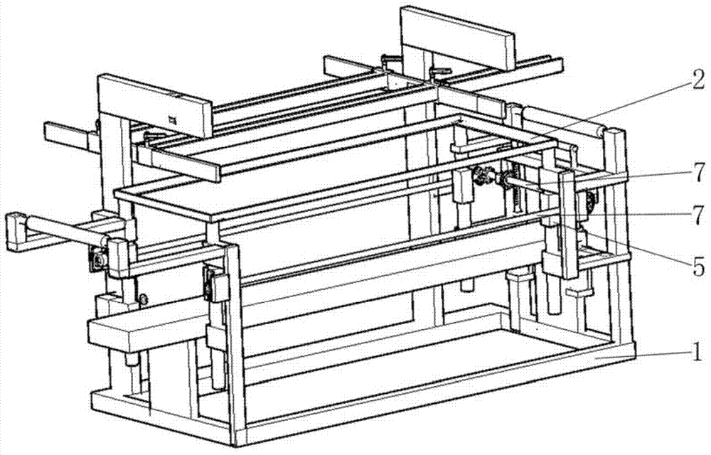
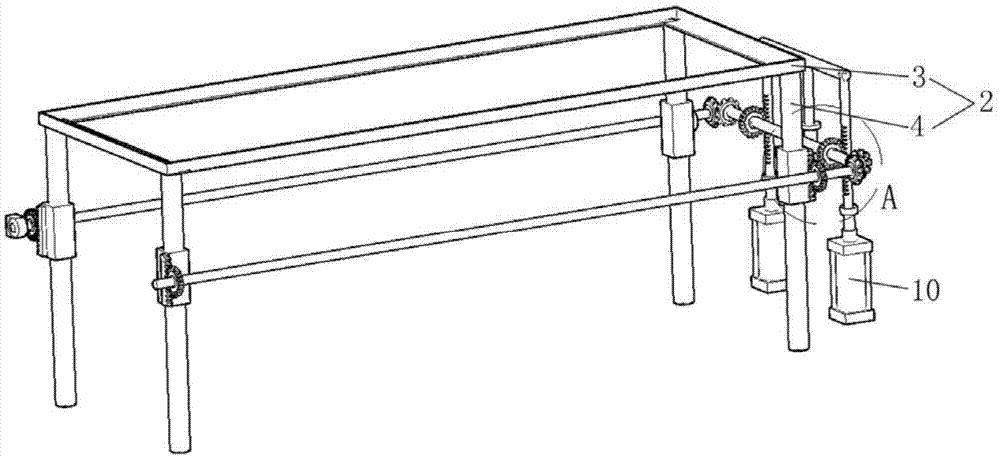
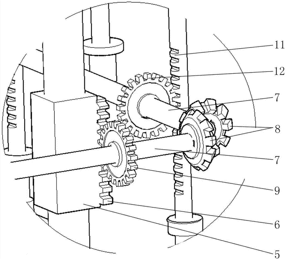
[0061] Such as figure 1 , 2 , The drilling machine shown in 3 has a bearing platform 2 installed on the frame 1 . In the first embodiment, the carrying platform 2 is composed of a carrying frame 3 with a rectangular outer contour and four lifting columns 4 , and the lifting columns 4 are respectively arranged at four corners of the carrying frame 3 . Lifting blocks 5 are installed on each lifting column 4, and lifting racks 6 are formed on the lifting blocks 5. Each lifting column 4 is connected by a lifting transmission shaft 7 . Driven gears 8 are installed on the ends of each lifting transmission shaft 7 , and the driven gears 8 on each lifting transmission shaft 7 mesh with each other. In addition, a lifting gear 9 that meshes with the lifting rack 6 is also provided on the lifting transmission shaft 7 . Simultaneously, a lifting cylinder 10 is installed on the frame 1 , and a driving rack 11 is installed on the piston rod of the lifting cylinder 10 . On the lifting t...

Embodiment 2

[0068] The difference between this embodiment 2 and embodiment 1 is that, as Figure 14 , 15 As shown, the transmission mechanism on the forward drilling mechanism 24 is composed of a transmission gear 36, a driven driven gear 37, a synchronous belt 54 and a row of drill bit gears 38. The transmission gear 36 is installed on the output shaft of the driving motor 35 , and the driven transmission gear 37 is installed in the mounting seat 26 . The transmission gear 36 and the driven transmission gear 37 are connected by a synchronous belt 54 . The row drill bit gear 38 is installed on the row drill bit 32 and links to each other with the synchronous belt 54 .

Embodiment 3

[0070] Utilize the drilling machine in embodiment 1 to drill the method on plate, its concrete steps are:

[0071] a) placing the carrier substrate 57 on the carrier frame 3, so that the upper surface of the carrier substrate 57 is flush with the carrier frame 3; at this moment, the carrier platform 2 is in the starting position;

[0072] b) along Figure 16 The plate feeding direction shown, the plate is placed on the carrier substrate 57;

[0073] c) Move the sheet material so that one side of the sheet material along the longitudinal direction of the carrying platform 2 is attached to the drilling datum plate 52; then, move the slide block 46 on the lateral positioning guide rail 44 according to the specification of the sheet material, and adjust the slide block on the lateral positioning guide rail 44 position on block 46;

[0074] d) Control the piston rods of each positioning cylinder 47 on the lateral positioning guide rail 44 to go down; push the sheet material, let ...


PUM


Abstract

The invention discloses a novel hole drilling machine for processing plate materials. A carrying platform capable of ascending and descending relative to a machine frame is arranged on the hole drilling machine; plate materials to be processed are carried by the carrying platform. The hole drilling machine provided by the invention has the advantages that the structure is simple; the operation is convenient; the ascending or the descending of the carrying platform is utilized, and lateral side holes and front side holes of the plate materials can be directly processed; the plate material turning by production personnel is not needed; the positioning of the plate materials is not only limited on one standard plate; the use flexibility is greatly improved; the number of machine loading operation times of the plate materials is reduced; the damage to the plate materials during the operation is reduced; the work intensity of operators is greatly reduced; the hole drilling efficiency of the plate materials, particularly the plates for furniture is greatly improved, and the speed is three times or more than three times of that of an ordinary drill bar with the same drill bit group number. The invention also discloses a method using the hole drilling machine to process the plate materials.

Description

technical field [0001] The invention relates to the field of woodworking machinery, in particular to a novel drilling machine and drilling method for processing boards. Background technique [0002] In the production of panel furniture, in order to improve the drilling efficiency on the panel, row drills are generally used for processing. Existing row drills are generally single-row or multi-row fixed row drill machines. The positions of the row drill upper drills or row drill assemblies on the machine tools are fixed. Although the drilling efficiency has been improved, However, due to the limitation of the structure, when it is necessary to drill holes with different hole distances on the workpiece, it is necessary to use a row of drills of corresponding specifications, resulting in high equipment costs; inconvenient. [0003] In order to improve the efficiency of row drilling, technical personnel in the industry have conducted research on row drilling with adjustable dri...

Claims


Application Information

Patent Timeline
IPC IPC(8): B27C3/00
CPCB27C3/00
Inventor 何有港
Owner 何有港
Why Eureka
Try Eureka