Aircraft oil tank inerting device based on catalytic oxidation technology

A technology of catalytic oxidation and fuel tank, which is applied in the direction of fuel tank safety measures, etc., can solve the problems of high price, narrow scope of application, low efficiency of OBIGGS, etc., and achieve the effect of fast start-up speed, high reliability, and low requirement for gas source purity

Inactive Publication Date: 2015-08-19
NANJING UNIV OF AERONAUTICS & ASTRONAUTICS
View PDF8 Cites 17 Cited by
  • Summary
  • Abstract
  • Description
  • Claims
  • Application Information

AI Technical Summary

Problems solved by technology

[0007] The purpose of the present invention is to overcome the shortcomings of low efficiency, high price and narrow application range of OBIGGS

Method used


Image

  • Aircraft oil tank inerting device based on catalytic oxidation technology
  • Aircraft oil tank inerting device based on catalytic oxidation technology
  • Aircraft oil tank inerting device based on catalytic oxidation technology

Examples


Embodiment 1

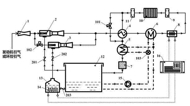
[0030] figure 1 It is an aircraft fuel tank inerting device based on catalytic oxidation technology of the present invention. The outlet of the voltage stabilizer 1 is connected to the primary inlet of the first gas injector 2 and the inlet of the second shut-off valve 102 through pipelines, and the outlet of the second shut-off valve 102 is connected through pipelines. It is connected with the secondary flow inlet of the second gas injector 2, the mixing outlet of the first gas injector 2 and the mixing outlet of the second gas injector 3 are connected with the inlet of the cold side channel of the regenerator 4 through pipelines, and the regenerator 4 is cooled Between the outlet of the side channel and the inlet of the second flame arrester 11, the hot side channel of the second cooler 6, the gas electric heater 8, the first flame arrester 9 and the catalytic reactor 10 are connected in sequence through pipelines, and the outlet of the second flame arrester 11 The pipelines...

Embodiment 2

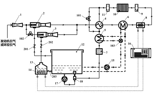
[0035] figure 2 It is a schematic flow diagram of the catalytic oxidation inerting device using injectors to wash fuel oil in this embodiment. In this implementation, the inlet of the voltage regulator (1) is connected to the air inlet of the environmental control, and the outlet of the water eliminator 7 is connected to the gas inlet of the washing injector 18 through a pipeline. Connection, the oil pump 17 is connected through a pipeline between the fuel outlet at the bottom of the fuel tank 12 and the fuel inlet of the washing injector 18, and the outlet of the washing injector 18 is below the lowest liquid level at the bottom of the fuel tank 12.

[0036] The working process difference of present embodiment and embodiment 1 is:

[0037] The inert gas leaving the water eliminator 7 no longer enters the upper inert gas inlet of the fuel tank 12, but flows into the gas inlet of the scrubber injector 18, and mixes with the fuel pumped in from the fuel tank 17 in the scrubber ...

Embodiment 3

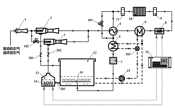
[0039] image 3 It is a schematic flow diagram of the catalytic oxidation inerting device using distributors to wash fuel oil in this embodiment. In this embodiment, the outlet of the water eliminator 7 is connected to the inlet of the gas distributor 19 through a pipeline, and the outlet of the gas distributor 19 is at the bottom of the fuel tank 12. face down.

[0040] The difference between this embodiment and Embodiment 2 is that the oil pump 12 and the scrubbing injector 18 in Embodiment 2 are replaced by a gas distributor 19, the inert gas flows into the inlet of the gas distributor 19, and flows into the inert gas main pipe through the inert gas inlet pipe 1001 1002, and then flow into the inert gas branch pipe 1003, a large number of inert gas small holes 1004 are opened on the inert gas branch pipe 1003, and finally the inert gas bubbles are formed and enter the fuel oil in the fuel tank 12. As the bubbles rise, the carbon dioxide and nitrogen in the inert gas and the...


PUM


Abstract

The invention discloses an aircraft oil tank inerting device based on a catalytic oxidation technology. High-pressure gas is imported into the device through an engine or an environmental control system, fuel oil steam and mixture other gas in gaseous phase space of the upper portion of an oil tank or fuel oil steam generated by fuel oil electric heater heating in an oil storage tank are/is pumped by two gas ejectors respectively, mixture flammable gas ejected from the gas ejectors is regulated to appropriate temperature through a regenerator, coolers and a gas electric heater then an oxidizing reaction is generated in a catalytic reactor, the fuel oil steam is converted into carbon dioxide and water steam, inert gas which is departed from the water steam is sent to the gaseous phase space of the upper portion of the oil tank or fuel oil of the lower portion of the oil tank, and an inerting aim is achieved. By adopting the technical scheme, the aircraft oil tank inerting device has the advantages that flowing and the mixture of the gas are completed by the gas ejectors, moving parts such as a draught fan are not needed, meanwhile the requirements of dive lowering and air filling increasing can be met, the structure is simple, and the operation is reliable.

Description

technical field [0001] The invention belongs to the technical field of fire prevention and explosion protection, and in particular relates to an aircraft fuel tank inerting device based on catalytic oxidation technology. Background technique [0002] The safety of modern aircraft has been widely concerned by the society, and fuel system combustion and explosion are one of the main causes of aircraft crashes. Statistics show that in the Vietnam War, the U.S. Air Force lost thousands of aircraft due to ground fire attacks. Among these losses, the proportion of losses due to fuel oil fires is as high as 50%. In NATO's investigation of 1,141 fire-related aircraft accidents, it was found that the main reason was caused by the explosion of the fuel tank after the flight or crash. Of course, during refueling and maintenance, it is also possible to cause the fuel tank to burn and explode. [0003] It can be seen that, no matter for military aircraft or civil aircraft, effective...

Claims


Application Information

Patent Timeline
IPC IPC(8): B64D37/32
Inventor 冯诗愚李超越刘卫华
Owner NANJING UNIV OF AERONAUTICS & ASTRONAUTICS
Why Eureka
Try Eureka