PCB transmission device

A conveying device and PCB board technology, applied in the directions of transportation and packaging, object supply, positioning objects, etc., can solve the problems of errors, difficulty in reducing the longitudinal height of the PCB board transmission and positioning structure, elastic deformation of the conveyor belt, etc., so as to prolong the service life. , not easy to deform, enhance the effect of strength

Inactive Publication Date: 2015-08-19
NEODEN TECH CO LTD
View PDF8 Cites 6 Cited by
  • Summary
  • Abstract
  • Description
  • Claims
  • Application Information

AI Technical Summary

Problems solved by technology

The PCB board transmission and positioning structure of the existing placement machine is relatively bulky. After the conveyor belt transports the PCB board to the placement station, the pressing mechanism below it presses the PCB board to the upper pressing plate or the lower surface of the pressing plate is fixed. Mounting, such as the top plate mechanism in the invention patent publication number CN 103025077A, and the lifting platform mentioned in CN 104202914 A, the above-mentioned top pressure mechanism all includes a cylinder, so it is difficult to reduce the longitudinal height of the PCB board transmission and positioning structure, and The strength of the existing conveyor belt is not enough to support the PCB board for placement. Forcible placement will cause elastic deformation of the conveyor belt, resulting in large errors

Method used


Image

  • PCB transmission device
  • PCB transmission device
  • PCB transmission device

Examples


Embodiment 1

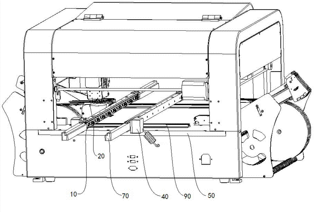
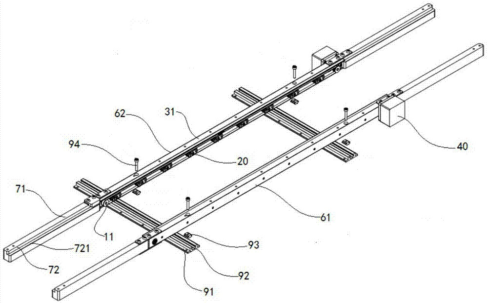
[0044] Embodiment 1: as Figures 1 to 5 As shown, the transmission mechanism 10 is composed of a transmission wheel 11 and a transmission belt 12, and the driving mechanism 40 is a motor, which drives the transmission wheel 11 to rotate.

[0045] Elastic supporting mechanism 20 comprises elastic part 21 and supporting head 22, and elastic part 21 is made up of rotating shaft 211, torsion spring 212, first side plate 213A, second side plate 213B, stress axis 214, torsion spring 212, first side plate 213A and the second side plate 213B are sleeved on the rotating shaft 211, the torsion spring 212 is sandwiched between the first side plate 213A and the second side plate 213B, and installed between the first side plate 213A and the second side plate 213B There is a stress shaft 214, and one end of the torsion spring 212 is fixed on the rotating shaft 211, and the other end is fixed on the stress shaft 214; One end away from the rotating shaft 211 is fixed between the first side p...

Embodiment 2

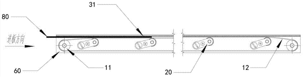
[0051] Embodiment 2: as Figure 6 As shown, the rest of the structure of this embodiment is the same as that of Embodiment 1, the main difference is that the guide mechanism 60 is omitted, and the suppression mechanism 30 includes a support side plate 32 and a pressing piece 31 arranged beside the transmission mechanism 10, and the support side plate 32 is not Attached to the conveyor belt 12, the supporting side plate 32 supports the pressing piece 31 so that it is located directly above the conveying mechanism 10. Since the PCB board 80 is always pressed under the pressing piece 31, the lateral offset of the PCB board 80 is not large. Existing placement machines are often equipped with a vision correction system, which can identify the offset error of the PCB board 80. As long as the conveyor belt 12 can withstand the impact of the placement operation without deformation, there will be no large deviation.

Embodiment 3

[0052] Embodiment 3: as Figure 7 As shown, the rest of the structure of this embodiment is the same as that of Embodiment 1, the main difference is that the elastic support mechanism 20 includes an elastic member 21 and a support head 22, and the elastic member 21 is composed of a rotating shaft 211, a torsion spring 212, a first The side plate 213A is composed of a torsion spring 212 and the first side plate 213A are sleeved on the rotating shaft 211, and a stress hole 215 is opened on the first side plate 213A close to the torsion spring 212, and one end of the torsion spring 212 is fixed on the rotating shaft 211, the other end is the stress end 216 fixed in the stress hole 215; the support head 22 is composed of a bearing 221 and an installation shaft 222, the bearing 221 is sleeved on the installation shaft 222, and the installation shaft 222 is fixed on the first side plate 213A away from the rotation One end of the shaft 211.


PUM


Abstract

The invention relates to a PCB transmission device, in particular to a PCB transmission device which is used for a small SMT automatic assembly printing process. The device comprises a transmission mechanism, an elastic bearing mechanism, a restraining mechanism, a driving mechanism and a machine base, wherein the transmission mechanism bears a PCB to move; the elastic bearing mechanism is used for enhancing the bearing strength of the transmission mechanism; the restraining mechanism is arranged above the transmission mechanism, and the lower contact surface of the transmission mechanism is smoother than the upper contact surface of the transmission mechanism; the driving mechanism is used for driving the transmission mechanism; all the mechanisms are mounted on the machine base; when the transmission mechanism loads, the elastic bearing mechanism jacks the PCB between the lower contact surface of the transmission mechanism and the upper contact surface of the transmission mechanism. The PCB transmission device has the advantages that the structure design is reasonable, the longitudinal height is small, the service life is long, and the device can bear the mounting intensity of a mounting head and cannot deform.

Description

technical field [0001] The invention relates to a PCB board conveying device, in particular to a PCB board conveying device used in a small SMT automatic assembly printing process. Background technique [0002] Surface Mount Technology (SMT for short) is a new generation of electronic assembly technology, which compresses traditional electronic components into devices with only a few tenths of the volume, thus realizing high-density, high-reliability, Miniaturization, low cost, and automation of production. The process method of assembling components on the PCB is called SMT process, and the related assembly equipment is called SMT equipment. The placement machine is a device used to realize high-speed, high-precision and fully automatic placement of components. It is the most critical and complex equipment in the entire SMT production. At present, it has developed from an early low-speed mechanical placement machine to a high-speed optical centering placement machine, and...

Claims


Application Information

Patent Timeline
Patent Type & Authority Applications(China)
IPC IPC(8): B65H5/02B65H5/36B65H9/04
CPCB65H5/02
Inventor 翁建永高其良
Owner NEODEN TECH CO LTD
Why Eureka
Try Eureka