
Evaporation source device and evaporation device

A technology of evaporation source and driving device, which is applied in the field of evaporation source device and evaporation device, can solve the problems of organic material decomposition or deterioration, uneven heat transfer, poor thermal conductivity, etc., to reduce material decomposition or deterioration, improve uniformity, The effect of improving the yield rate

Inactive Publication Date: 2015-08-19
BOE TECH GRP CO LTD
View PDF2 Cites 1 Cited by
  • Summary
  • Abstract
  • Description
  • Claims
  • Application Information

AI Technical Summary

Problems solved by technology

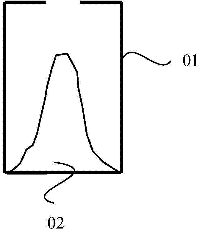
[0005] like figure 1 as shown, figure 1 It is a schematic diagram of the structure of the existing evaporation source device. The evaporation source device includes a crucible 01 containing organic materials. The crucible 01 is heated to realize the evaporation of organic materials in the crucible 01. Since the heating of the crucible 01 only affects the surrounding area of ​​the crucible 01 For the organic material in the crucible tank of crucible 01, the thermal conductivity of the organic material itself is poor, and the heat conduction path is long, which is easy to cause uneven heat transfer, especially for large-sized evaporation sources. , the phenomenon of uneven temperature distribution is more obvious, which in turn causes problems such as insufficient stability of the deposition rate of the evaporation of organic materials and a decrease in yield.
[0006] like figure 1 As mentioned above, for the sublimation-type OLED organic material, during the evaporation process, the organic material close to the crucible wall in the crucible will be sublimated earlier because it is heated first, while the organic material in the central part will be gradually formed when heated slowly. Upright island structure 02, and in order to maintain a stable evaporation rate, the evaporation source will continue to increase the temperature, which will cause more heat in the organic material in the crucible and in contact with the bottom of the crucible, resulting in decomposition or deterioration of the organic material, resulting in material waste and pollution, and even affect the performance of OLED devices

Method used


Image

  • Evaporation source device and evaporation device
  • Evaporation source device and evaporation device
  • Evaporation source device and evaporation device

Examples


Embodiment Construction

[0035] The following will clearly and completely describe the technical solutions in the embodiments of the present invention with reference to the accompanying drawings in the embodiments of the present invention. Obviously, the described embodiments are only some, not all, embodiments of the present invention. Based on the embodiments of the present invention, all other embodiments obtained by persons of ordinary skill in the art without making creative efforts belong to the scope of patent protection of the present invention.

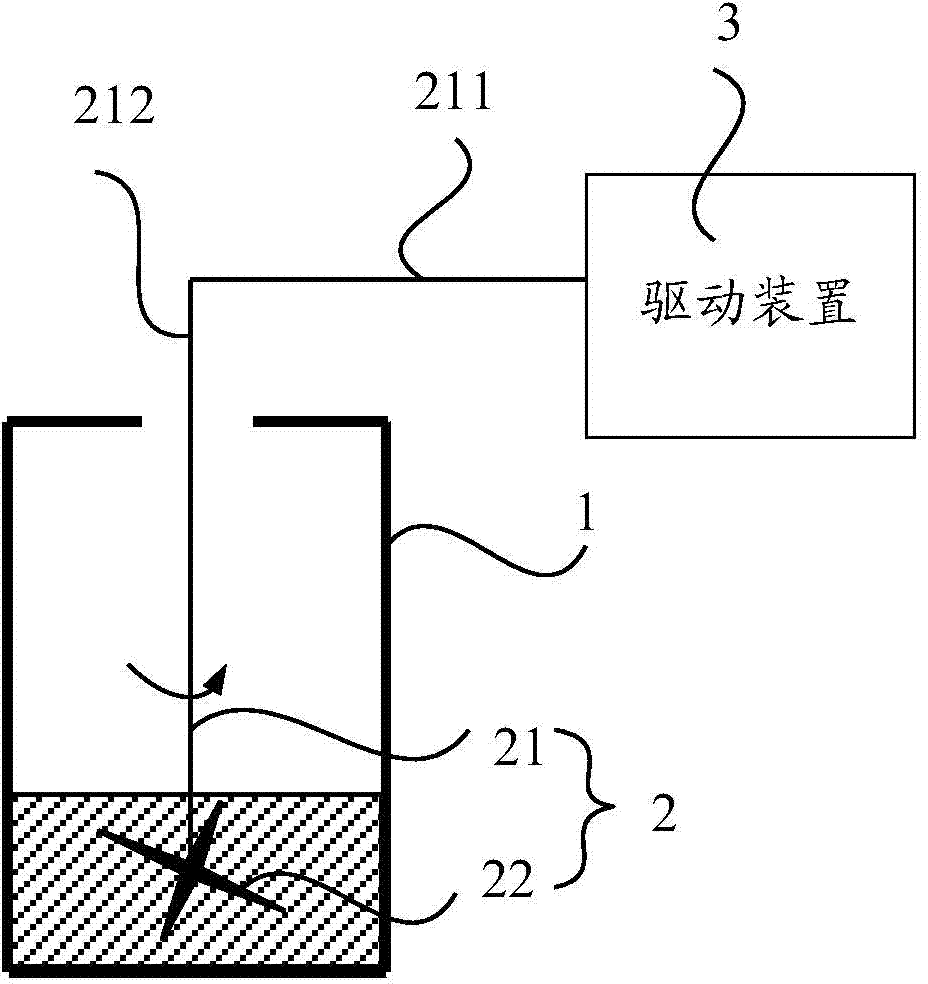
[0036] Such as figure 2 as shown, figure 2 The first structural schematic diagram of the evaporation source device provided by the embodiment of the present invention; the embodiment of the present invention provides an evaporation source device, including:

[0037] A crucible 1 open at one end;

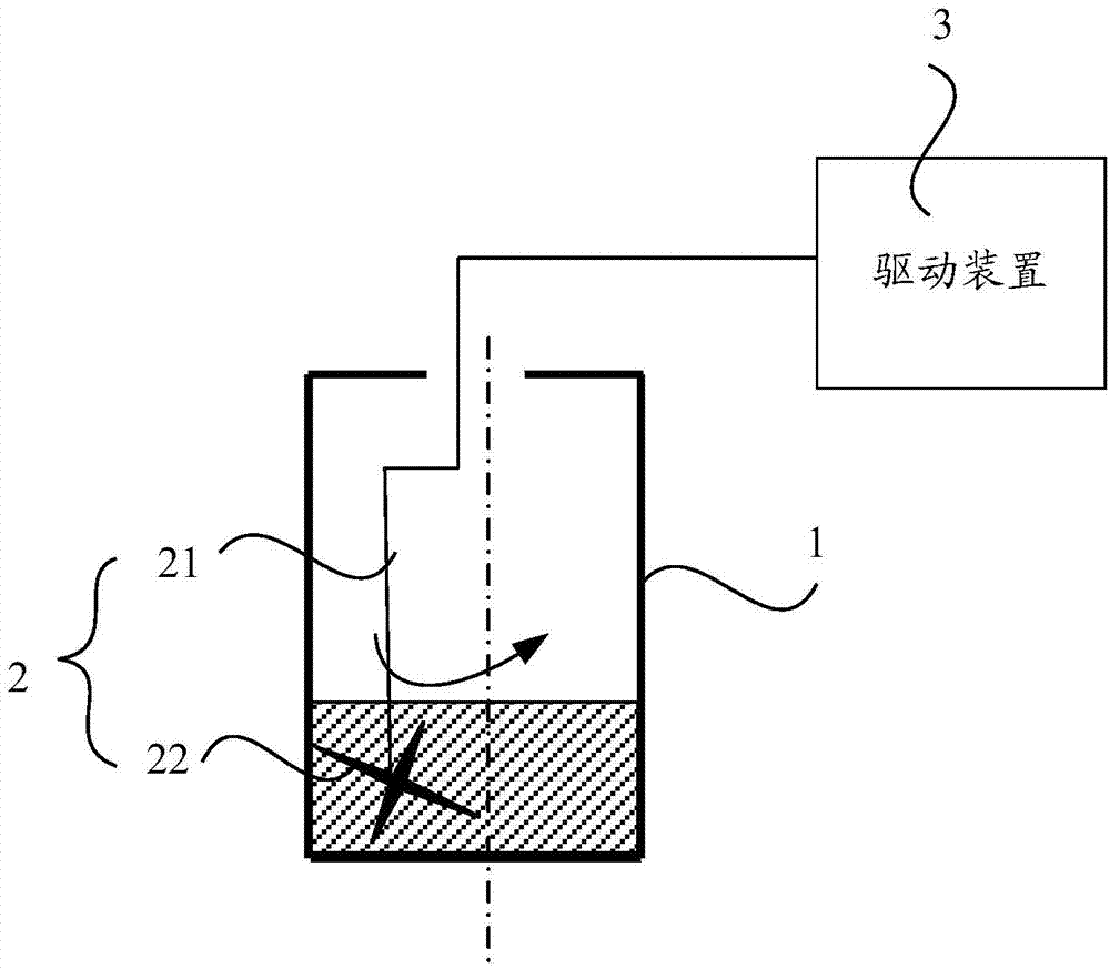
[0038] a stirring unit 2 located in the crucible 1 and stirring the material in the crucible 1;

[0039] A driving device 3 that drives the stirring u...


PUM


Abstract

The invention relates to the technical field of evaporation equipment and discloses an evaporation source device and an evaporation device which are used for improving the uniformity of material heating and further increasing the yield of material evaporation and improving the properties of display devices. The evaporation source device comprises a crucible, a stirring unit and a driving device, wherein one end of the crucible is an open end; the stirring unit is located in the crucible and used for stirring material in the crucible; and the driving device is used for driving the stirring unit to rotate. The evaporation source device provided by the invention has the beneficial effects that material in the crucible can be stirred by the stirring unit so that the contact area between the material and the side wall of the crucible is always largest, thereby reducing the occurrence of problem that the material is partially heated too much and further reducing the occurrence of a phenomenon that the material is decomposed or degraded.

Description

technical field [0001] The invention relates to the technical field of evaporation equipment, in particular to an evaporation source device and an evaporation device. Background technique [0002] In recent years, organic electroluminescence display (OLED), as a new type of flat panel display, has gradually received more attention. Due to its active light emission, high luminous brightness, high resolution, wide viewing angle, fast response speed, low energy consumption, and flexibility, it has become a next-generation display technology that may replace liquid crystal display. [0003] Evaporation devices are experimental and production equipment used in the field of thin film preparation, and are widely used in organic optoelectronic fields such as organic light-emitting diodes (OLEDs), organic solar cells (OPVs), and organic field-effect transistors (OFETs). [0004] Organic Light-Emitting Diode (OLED for short) manufactures a carrier transport layer and an organic light...

Claims


Application Information

Patent Timeline
Patent Type & Authority Applications(China)
IPC IPC(8): C23C14/24
CPCC23C14/12C23C14/243
Inventor 矫士博
Owner BOE TECH GRP CO LTD
Learn More