Automatic calibration system and method for electronic-controlled engine fuel oil parameters

An electronically controlled engine and calibration system technology, applied in engine components, engine control, engine testing, etc., can solve problems such as error-prone and large workload, and achieve the effect of reducing work intensity and test error rate

Inactive Publication Date: 2015-08-19
TONGJI UNIV
4 Cites 7 Cited by

AI-Extracted Technical Summary

Problems solved by technology

[0007] In view of the shortcomings of the prior art described above, the purpose of the present invention is to provide an automatic calibration system and method for fuel parame...

Abstract

The invention provides an automatic calibration system and method for electronic-controlled engine fuel oil parameters. The method comprises the steps that according to three calibration modes of dots, lines and faces, oil injection parameters and the variation range of the oil injection parameters are selected to conduct the experiment design; according to position definition variables of the oil injection parameters on a screen and the input sequence of the variables, a computer operating system API is called to generate the automatic calibration system of a fuel oil injection system and control the calibration process of the engine fuel oil system. The oil injection parameters of the fuel oil system are controlled through the automatic calibration system of the fuel oil injection system, then the whole calibration process of the engine fuel oil system is controlled, and finally the automation of the electric engine calibration process is achieved. Accordingly, an engine can operate within different oil injection parameter combinations under a certain working condition when the oil injection parameters are within a certain range, the power performance, the economical efficiency and the emission performance of the engine under different oil injection parameter combinations can be measured, and the labor intensity of calibration engineers and the experiment error rate are reduced.

Application Domain

Electrical controlEngine testing +3

Technology Topic

Power performanceError ratio +4

Image

  • Automatic calibration system and method for electronic-controlled engine fuel oil parameters
  • Automatic calibration system and method for electronic-controlled engine fuel oil parameters
  • Automatic calibration system and method for electronic-controlled engine fuel oil parameters

Examples

  • Experimental program(4)

Example Embodiment

[0059] Example one
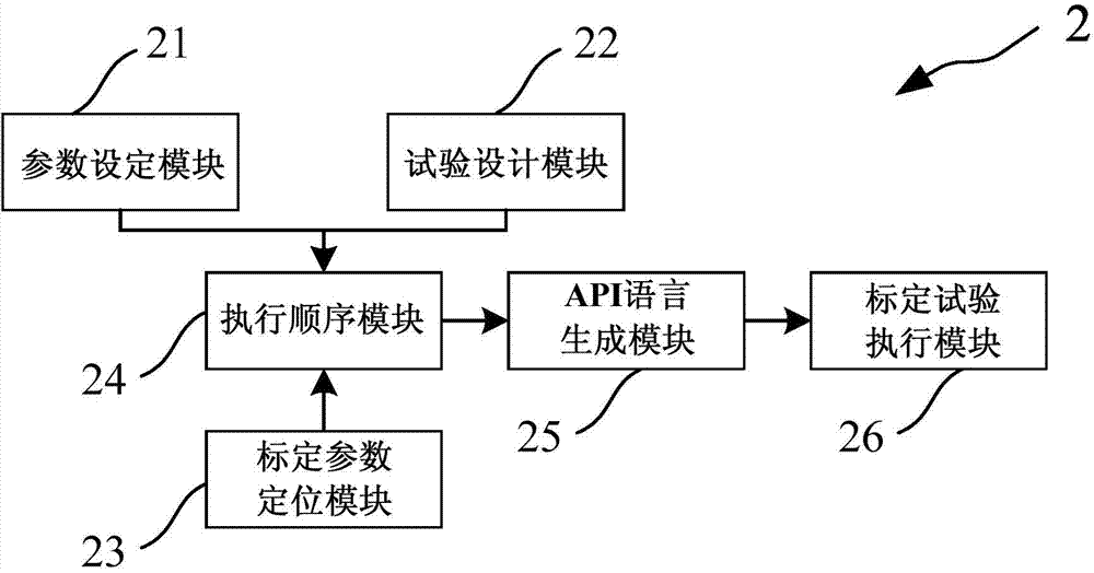
[0060] Such as figure 2 As shown, the present invention provides an automatic fuel parameter calibration system 2 of an electronic control engine, which includes:
[0061] The parameter setting module 21, the experiment design module 22, the calibration parameter positioning module 23, the execution sequence module 24, the API language generation module 25, and the calibration experiment execution module 26.
[0062] The parameter setting module 21 is used to select fuel injection parameters and set the range of the fuel injection parameters. In this embodiment, the fuel injection parameters include main fuel injection volume, number of fuel injector holes, fuel injector aperture, rail pressure, or fuel injection timing. In this embodiment, the parameter setting module 21 is an application program module, which needs to call the API interface to control the operating system to realize the selection of the fuel injection parameter and the setting of the fuel injection parameter range.
[0063] The test design module 22 is connected to the parameter setting module 21, and the test plan is determined according to the calibration mode and the number and range of the fuel injection parameters. The calibration mode includes point calibration mode, line calibration mode and surface calibration mode. In the point calibration mode, the space filling test design method is adopted, and the test plan is formulated according to the number and range of the injection parameters selected in the parameter setting module 21. In the online calibration mode, the calibration path is formulated according to the spline curves of different characteristic parameters, and the experimental design method of the full factor method, Taguchi method or Latin method is adopted to determine the test plan. In the surface calibration mode, the calibration range is established according to the spline surfaces of different characteristic parameters, and the experimental design method of the full factor method, Taguchi method or Latin method is adopted to determine the test plan. In this embodiment, the test design module 22 is an application program module, which needs to call an API interface to control the operating system to realize the determination of the test plan.
[0064] The calibration parameter positioning module 23 is used to determine the calibration position of the fuel injection parameter. In this embodiment, the calibration parameter positioning module 23 is an application program module, which needs to call an application program interface to control the operating system to determine the calibration position of the fuel injection parameter.
[0065] The execution sequence module 24 is connected to the parameter setting module 21, the experimental design module 22 and the calibration parameter positioning module 23, and is used to obtain the value of the fuel injection parameter through the parameter setting module 21, and The test design module 22 obtains the test plan, obtains the calibration position of the fuel injection parameter through the calibration parameter positioning module 23, and obtains the calibration position of the fuel injection parameter according to the value of the fuel injection parameter, the test plan, and the calibration of the fuel injection parameter The location determines the execution sequence of the calibration test process. In this embodiment, the execution sequence module 24 is an application program module, and an API interface needs to be called to control the operating system to determine the execution sequence of the test process.
[0066] The API language generation module 25 is connected between the execution sequence module 24 and the calibration test execution module 26, and is used to convert the test process into the calibration according to the fuel injection parameters and the test plan API language that can be read by the test execution module 26.
[0067] The calibration test execution module 26 is connected to the execution sequence module 24 and is used to control the engine to execute the calibration test according to the test procedure. In this embodiment, the calibration test execution module 26 is an internal module of the operating system and needs to exchange information with other modules through an API interface.

Example Embodiment

[0068] Example two
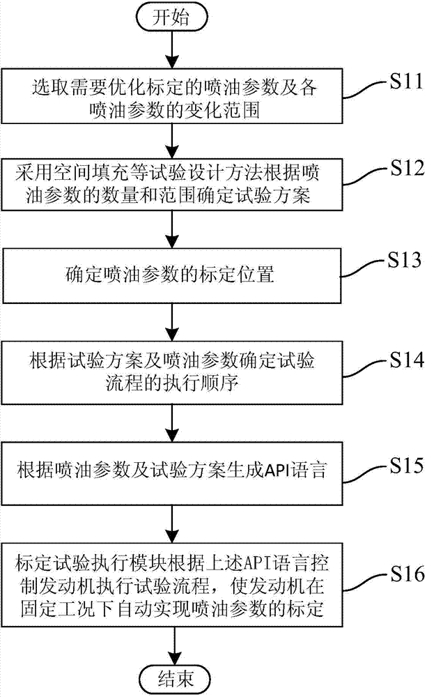
[0069] Such as image 3 As shown, the present invention provides an automatic calibration method for an electronically controlled engine fuel parameter automatic calibration system based on a point calibration mode. The point calibration mode is suitable for optimizing the calibration of the fuel injection parameter combination under a certain operating condition point, including the following steps:
[0070] Step S11: The parameter setting module 21 calls the API interface to select the fuel injection parameters to be optimized and calibrated and the variation range of the fuel injection parameters.
[0071] Specifically, in this embodiment, the fuel injection parameters are selected as rail pressure and fuel injection timing, the rail pressure change range is set to 90-130 MPa, and the fuel injection timing change range is set to 0~20 crankshaft angle.
[0072] Step S12: The test design module 22 calls the API interface, and uses test design methods such as space filling to determine the test plan according to the number and range of the fuel injection parameters.
[0073] Specifically, according to the test requirements, a space filling test design method is adopted for one operating point of the engine, so that the fuel injection timing is within the range of 0-20 crankshaft angle, and the rail pressure is varied within the range of 90-130 MPa to obtain different injection timings. Combination of fuel injection parameters at time and fuel injection rail pressure to determine the test plan.
[0074] Step S13: The calibration parameter positioning module 23 calls the API interface to determine the calibration position of the fuel injection parameter in the calibration software. Such as Figure 4 As shown, in this embodiment, the calibration parameters in the calibration parameter positioning module 23 include: manual mode enable, rail pressure enable, rail pressure, fuel injection timing enable, fuel injection timing, among which, manual Mode enable is A coordinate, rail pressure enable is B coordinate, rail pressure is C coordinate, fuel injection timing enable is D coordinate, and fuel injection timing is E coordinate.
[0075] Step S14: The execution sequence module 24 calls the API interface, and determines the execution sequence of the test process according to the test plan and the fuel injection parameters. The execution sequence is the cycle of operating system interface initialization, fuel injection parameter data import, engine running stabilization and data collection. Such as Figure 5 As shown, open the operating system interface and initialize. Next, move the mouse to the A coordinate and set it to 0; move the mouse to the B coordinate and set it to 1; move the mouse to the C coordinate and set it to the corresponding value in the test plan; move the mouse to the D coordinate, and Set it to 1; move the mouse to the E coordinate and set it to the corresponding value of the test plan; where 0 means not selected, 1 means selected, that is, the rail pressure and the fuel injection timing are selected and assigned corresponding values. Synchronize the fuel injection parameter data so that the engine runs according to the fuel injection parameter combination; and collect the test data after the engine is stabilized. After completion, enter the next cycle. After all the test cycles are over, move the mouse to the A, B, C, D, and E coordinates in turn, and set them to 0.
[0076] Step S15: Based on the API language generating module 25, according to the fuel injection parameters and the test plan, convert the test process into the API language.
[0077] Step S16: Invoke the calibration test execution module 26 to perform a calibration test, so that the engine automatically realizes the calibration of fuel injection parameters according to the test plan under a fixed operating condition.

Example Embodiment

[0078] Example three
[0079] Such as Image 6 As shown, the present invention provides an automatic calibration method for an electronically controlled engine fuel parameter automatic calibration system based on the line calibration mode. The surface line calibration mode is suitable for the optimization of a certain injection parameter during transient operating conditions or excessive operating conditions. It includes the following steps:
[0080] Step S21: The parameter setting module 21 calls the API interface to select the fuel injection parameters to be optimized and calibrated and the variation range of the fuel injection parameters. In this embodiment, the main fuel injection volume and fuel injection timing are selected as the fuel injection parameters.
[0081] Step S22: The test design module 22 calls the API interface, determines the starting and ending conditions of the calibration path, and formulates the calibration path according to the spline curve of different characteristic parameters, using the full factor method, Taguchi method or Latin method The test design method determines the test plan.
[0082] Select the starting working condition point and the ending working condition point that need to be optimized and changed, and use the method of spline curve to calculate other working condition points that need to be calibrated to obtain the calibration path. Different calibration paths are determined by changing the characteristic parameters to obtain the test plan.
[0083] Step S23: The calibration parameter positioning module 23 calls the API interface to determine the calibration position of the fuel injection parameter in the calibration software. Such as Figure 7 As shown, in this embodiment, the calibration parameters in the calibration parameter positioning module 23 include: the positions of the operating point on the calibration path 1 to the calibration path 5, where in the calibration path 1, the operating point 1 is A Coordinates, working condition point 2 is B coordinate, working condition point 3 is C coordinate... Working condition point n is N coordinate; in calibration path 2, working condition point 1 is a coordinate, working condition point 2 is b coordinate, working condition Point 3 is the c coordinate...the working condition point n is the n coordinate. According to the test plan, the coordinates of each operating point on the different calibration paths are determined, which will not be repeated here.
[0084] Step S24: The execution sequence module 24 calls the API interface, and determines the execution sequence of the test process according to the test plan and the fuel injection parameters. The execution sequence is the cycle of operating system interface initialization, fuel injection parameter data import, engine operation and stability, and data acquisition. Such as Figure 8 As shown, first open the operating system interface for initialization, and open the main fuel injection volume coordinate map. Next, move the mouse to the A coordinate and set it to the corresponding fuel injection value in the test plan; ... Move the mouse to the N coordinate and set it to the corresponding fuel injection value in the test plan. Synchronize the fuel injection parameter data to make the engine run according to the fuel injection parameter combination; and collect the test data after the engine is stable. After completion, enter the next calibration path. After all the paths are completed, you can perform a calibration test on the next injection parameters that need to be optimized.
[0085] Step S25: Based on the API language generating module 25, according to the fuel injection parameters and the test plan, convert the test process into the API language.
[0086] Step S26: Invoke the calibration test execution module 26 to perform a calibration test, so that the engine automatically realizes the calibration of the fuel injection parameters according to the test plan under a fixed operating condition.

PUM

no PUM

Description & Claims & Application Information

We can also present the details of the Description, Claims and Application information to help users get a comprehensive understanding of the technical details of the patent, such as background art, summary of invention, brief description of drawings, description of embodiments, and other original content. On the other hand, users can also determine the specific scope of protection of the technology through the list of claims; as well as understand the changes in the life cycle of the technology with the presentation of the patent timeline. Login to view more.
Why Eureka
Try Eureka