Eureka AIR delivers breakthrough ideas for toughest innovation challenges, trusted by R&D personnel around the world.

Tray piston type swing driving machine capable of mechanically driving a piston to act on fluid load

A mechanically driven, fluid-loaded technology, applied in the direction of oscillating piston machinery, oscillating piston pumps, components of pumping devices for elastic fluids, etc., can solve problems such as low corrosion resistance, complex structure, and low mechanical efficiency

Active Publication Date: 2015-08-19
桐乡市中元建材科技有限公司
View PDF5 Cites 9 Cited by
  • Summary
  • Abstract
  • Description
  • Claims
  • Application Information

AI Technical Summary

Problems solved by technology

[0002] There are centrifugal pumps, plunger pumps and piston compressors in the existing disclosed pressure-feeding fluid machines. The stress intensity occurring in the dynamic process presents a high-level transmission from small to large. As the highest stress-bearing parts, cranks, connecting rods, and pins become weak links that affect life. Due to the need to meet the strength requirements of large peak stress , many parts are basically made of metal materials, and the anti-corrosion performance of metal materials is significantly lower than that of organic composite materials; these mechanical parts have many types, complex structures, high costs, and low mechanical work efficiency
In the existing public information, we have not found any similar information about the mechanically driven piston acting on the fluid load of the tray piston type swing drive machine

Method used

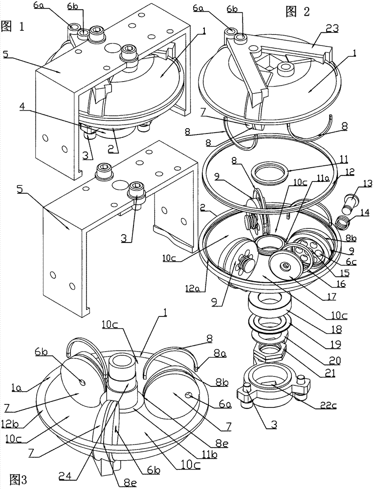
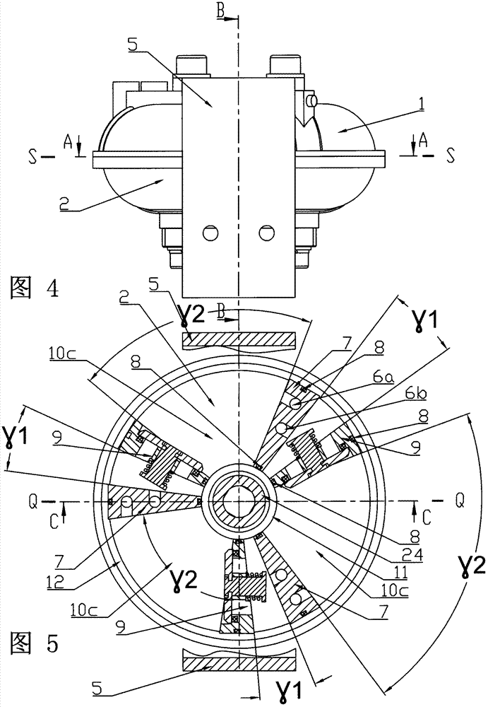
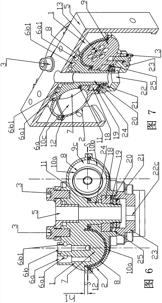

Image

  • Tray piston type swing driving machine capable of mechanically driving a piston to act on fluid load
  • Tray piston type swing driving machine capable of mechanically driving a piston to act on fluid load
  • Tray piston type swing driving machine capable of mechanically driving a piston to act on fluid load

Examples


Embodiment 2

[0073] refer to Figure 29 and 30 , as a partial embodiment 2 of the detachable piston sheet combined with the tray groove;

[0074] Shown in the figure is the detachable piston plate of oblong outline 29a, which is provided with a protruding ring 44 larger than the cross-sectional profile of the tray groove at the joint with the keyway, the static seal of the detachable piston plate The part is a static seal half ring 44b, and a static seal half ring groove 44a with a depression along the tangential direction of the rotation center circle is also provided on the detachable piston plate. The static seal half ring 44b is arranged on the static seal half ring In the groove 44a, a convex groove 8b is provided on the sliding engagement surface of the piston plate and the groove of the tray, and the semi-ring sealing ring 8 is fixed in the convex groove on the piston plate matching the section of the static sealing half ring.

Embodiment 3

[0075] refer to Figure 31 and 32 , as yet another partial embodiment 3 of the detachable piston sheet combined with the tray groove;

[0076] In the figure, a part of the detachable piston plate with circular contour line 36b is inserted into the tray groove and fixed into a detachable combined structure, insert the joint part of the detachable piston plate on the tray groove and utilize the hole to tighten The firmware 3 is fixed; a static seal is provided between the joint surface of the detachable piston plate and the groove of the tray. The static seals of the detachable piston plate are two static seal half-rings 44b, and two static seal half-ring grooves 44a are provided with depressions along the tangent direction of the center circle of rotation on the detachable piston plate. The sealing half ring 44b is arranged in the static sealing half ring groove 44a; the fastener 3 for the hole is a screw, and the two screws are screwed on the threaded hole 36f of the detacha...

Embodiment 5

[0081] The difference between this embodiment and Embodiment 4 is that the mechanically driven piston acting on the fluid load system is a system in which the mechanically driven single-acting piston acts on the fluid load to deliver fluid in two directions. The groove of the fixed tray is provided with a combination of n pairs of double stationary piston pieces and double swinging piston pieces, each pair of combination has two stationary piston pieces and two swinging piston pieces; There is an independent working chamber 10c between the outer angle γ of the normal surface of the plumb bob of two stationary piston plates; an independent working chamber 10c is provided and communicated with n sets of inlet and exhaust pressure-feeding fluid passages, and the two stationary piston plates lead The wall of the fixed tray in the range where the inner included angle of the hammer surface is β is provided with an external drain fluid channel 6a, and a section of drain fluid channel ...


PUM


Abstract

The invention relates to a tray piston type swing driving mechanism capable of mechanically driving a piston to act on a fluid load. The angular stroke swing range of the machine is from 0 degree to 330 degrees or continuous rotate in a single-way manner, and the machine is particularly suitable for pumping fluid. The fluid of the driving machine pressure feeding piston driving machine load work or the fluid of mechanical driving piston pressure feeding load work can be gas or liquid. The driving machine comprises a tray piston type swing execution device, a fluid inlet and draining channel system, a cooling system and a driving force generation system. The fluid inlet and exhaust channel system comprises a fluid channel, a pipe opening and a valve, and the fluid channel is communicated with a working cavity; the cooling system carries out forced cooling and / or natural heat dissipation on an element of the driving machine; the driving force generation system is a system capable of enabling the mechanical driving piston to act on the fluid load; and the tray piston type swing execution device comprises two trays, a piston piece, a connecting mechanism, a power inlet and outlet bonding structure, a lubricating system and a sealing structure.

Description

technical field [0001] The invention relates to a tray piston type swing driving machine in which a mechanically driven piston of a pressure-feeding fluid acts on a fluid load, and the range of angular stroke swing of the swing piston piece is about 0-330°, which is suitable for driving the piston to press-feed the fluid for pumping work; The fluid that the mechanically driven piston of the drive machine sends is gas or liquid. Background technique [0002] There are centrifugal pumps, plunger pumps and piston compressors in the existing disclosed pressure-feeding fluid machines. The stress intensity occurring in the dynamic process presents a high-level transmission from small to large. As the highest stress-bearing parts, cranks, connecting rods, and pins become weak links that affect life. Due to the need to meet the strength requirements of large peak stress , Many parts are basically made of metal materials, and the anti-corrosion performance of metal materials is sign...

Claims


Application Information

Patent Timeline
IPC IPC(8): F16K31/122
CPCF04C9/005F04C15/0088F04C15/066F04C21/005F04C29/02F04C29/126F05B2240/30
Inventor 张民良
Owner 桐乡市中元建材科技有限公司
Why Eureka
Eureka Blog
Learn More