Multi-core array integrated structure for LED light source

A technology of LED light source and LED chip, which is applied in the direction of light source, light source fixing, semiconductor devices of light-emitting elements, etc., can solve the problems of high luminous flux, difficult to achieve surface density, etc. The effect of benefiting the organization of production

Inactive Publication Date: 2017-01-25
中山市美钰鑫光电科技有限公司
View PDF3 Cites 0 Cited by
  • Summary
  • Abstract
  • Description
  • Claims
  • Application Information

AI Technical Summary

Problems solved by technology

However, these packaging structures are difficult to meet the requirements of surface density and high luminous flux.

Method used


Image

  • Multi-core array integrated structure for LED light source
  • Multi-core array integrated structure for LED light source
  • Multi-core array integrated structure for LED light source

Examples


Embodiment 1

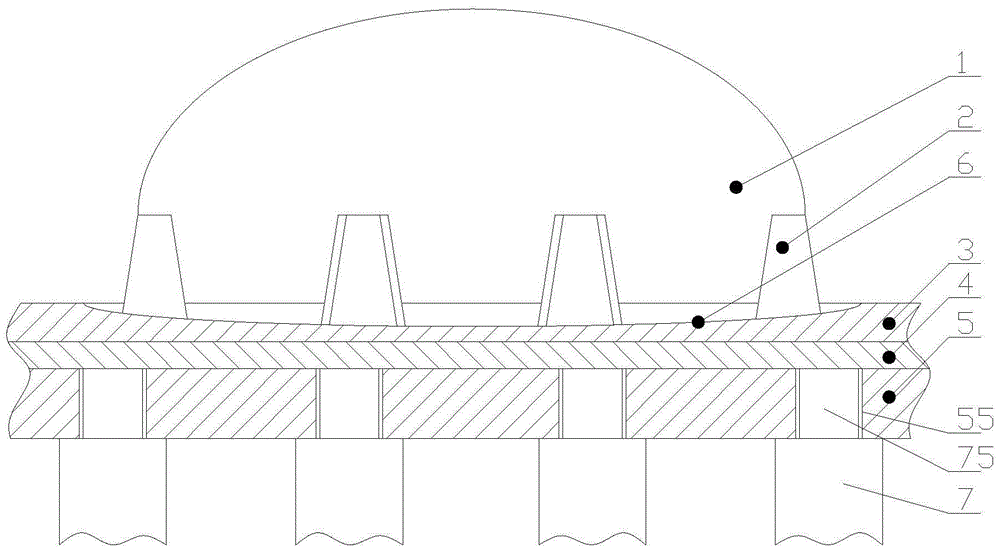
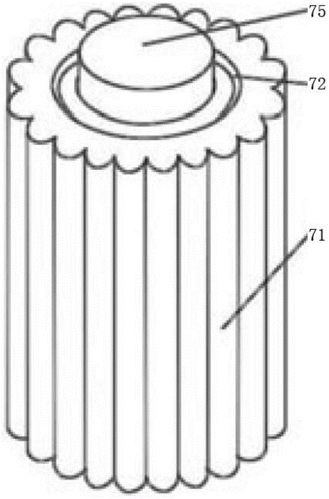
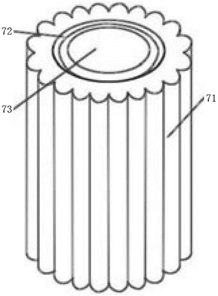
[0025] A multi-core array integrated structure for LED light source, which includes a substrate 5, the substrate 5 is provided with a printed circuit 3, the substrate 5 is an aluminum metal substrate 5, the printed circuit 3 and the substrate 5 are provided with a very thin spacer In the thermal layer 4, the upper end of the printed circuit 3 is recessed to form a cup-shaped groove 726. A number of LED chips 2 are welded in the cup-shaped groove 726, and the LED chips 2 are enclosed by a silicone resin layer 1. The printed circuit 3, the heat insulation layer 4, and the substrate 5 are glued together to form an integral heat dissipation structure 7. The number of LED chips 2 is 2N, where N is a natural number, so that it is convenient for the LED chips 2 to be connected in series and parallel. Under special circumstances, the number of LED chips 2 can also be considered as an odd number. The multi-chip integrated structure can also be used as a unit, and several units form a li...

Embodiment 2

[0032] On the basis of the first embodiment, a plurality of copper foils 511 are arranged on the top and bottom surfaces of the substrate 5 at preset positions, and the copper foil 511 on the bottom surface of the substrate 5 is additionally provided with a tin layer 513 to prevent oxidation, and A plurality of LED chips 2 are arranged on the top surface of each copper foil 511 in one-to-one correspondence, so that each LED chip 2 and each copper foil 511 form an electrothermal connection. The bottom surface of the LED chip 2 is provided with an insulating layer 521 in contact with the copper foil 511, a heat dissipation via 512 is provided at the position of the copper foil 511 in contact with the LED chip 2 on the substrate 5, and the inner cylindrical surface of the heat dissipation via 512 is also A copper foil 511 is provided, and the copper foil 511 on the inner cylindrical surface of the heat dissipation via 512 forms an electrothermal connection with the copper foil 511 ...


PUM


Abstract

The invention discloses a multi-core array integrated structure for an LED light source and belongs to the multi-core array integrated structure in the technical field of LED light source lighting. According to the technical scheme, the multi-core array integrated structure comprises an aluminum substrate provided with a printed circuit. A thermal insulating layer is disposed between the substrate and the printed circuit. The upper end face of the printed circuit is recessed to form a bowl-shaped groove. A plurality of LED chips are welded in the bowl-shaped groove. The LED chips are encapsulated by a silicon resin layer. A radiating structure is disposed below the substrate and comprises a radiator. A groove is formed in the middle of the upper end of the radiator. A hollow body is disposed at the bottom end of the groove. A thermal conducting column is disposed in the hollow body of the radiator. The thermal conducting column is provided with a protrusion exposed out of the upper end face of the radiator after the thermal conducting column is disposed in the hollow body. The protrusion is nested into the through hole of the substrate. The upper end face of the protrusion attaches to the lower end of the thermal insulating layer. The multi-core array integrated structure is high in brightness and good in radiating effect.

Description

Technical field [0001] The invention belongs to the technical field of LED light source lighting, and relates to a multi-core multi-core array integrated structure, in particular to a multi-core array integrated structure for LED light sources with higher brightness and better heat dissipation effect. Background technique [0002] Road lighting is an important part of urban lighting. Traditional street lamps often use high-pressure sodium lamps to emit light at 360 degrees. The disadvantage of large light loss causes a huge waste of energy. At present, the global environment is deteriorating day by day, and all countries are developing clean energy. With the rapid growth of the national economy, the contradiction between my country's energy supply and demand has become increasingly prominent, and there has been a serious shortage of power supply, and energy conservation is an urgent problem to be solved. [0003] With the continuous improvement of LED technology, LED street lights...

Claims


Application Information

Patent Timeline
Patent Type & Authority Patents(China)
IPC IPC(8): F21K9/20F21V19/00F21V29/70F21V29/85F21V29/503F21Y115/10
CPCF21V19/001
Inventor 于春满陆皓张兴杨婷
Owner 中山市美钰鑫光电科技有限公司
Why Eureka
Try Eureka