Medium-wave infrared continuous zooming camera shot and control method thereof

A zoom lens and infrared technology, applied in the lens field, can solve problems such as loss and blurred targets, and achieve the effects of improved vibration resistance, short magnification compensation stroke, and compact structure

Active Publication Date: 2015-08-19
FUJIAN FORECAM OPTICS CO LTD
View PDF5 Cites 25 Cited by
  • Summary
  • Abstract
  • Description
  • Claims
  • Application Information

AI Technical Summary

Problems solved by technology

Although the structure of the two-speed or three-speed zoom optical system is simple and easy to implement, it may cause the target to be blurred or lost during the switching process.

Method used


Image

  • Medium-wave infrared continuous zooming camera shot and control method thereof
  • Medium-wave infrared continuous zooming camera shot and control method thereof
  • Medium-wave infrared continuous zooming camera shot and control method thereof

Examples


Embodiment Construction

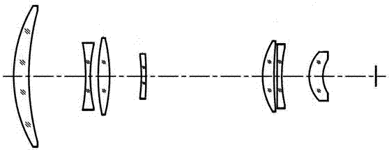
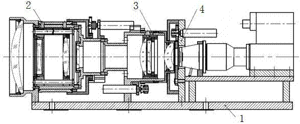
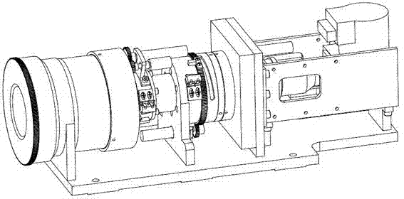
[0026] Such as Figure 1-8 As shown, a medium-wave infrared continuous zoom lens, the mechanical structure of the lens includes a zoom assembly, a focus assembly, and a detector assembly that are sequentially installed and connected to the connecting base plate from left to right, and the zoom assembly includes a front fixed lens A , variable power lens B, compensation lens C, rear fixed lens D and zoom mechanism, the focusing assembly includes secondary imaging lens group E and focusing mechanism, the detector assembly includes a baffle switching mechanism, a detector and a detector frame ; In the optical system of the lens, a front fixed lens A, a variable power lens B, a compensation lens C, a rear fixed lens D, and a secondary imaging lens group E are arranged successively along the incident direction of the light from left to right, and the secondary The imaging lens group E is sequentially provided with a positive lens E-1, a negative lens E-2 and a positive lens E-3, th...


PUM


Abstract

The invention relates to a medium-wave infrared continuous zooming camera shot and a control method thereof. The mechanical structure of the camera shot comprises a zooming assembly, a focusing assembly and a detector assembly which are installed on and connected to a connecting bottom plate sequentially from left to right. The zooming assembly comprises a front fixed lens A, a variable-magnification lens B, a compensation lens C, a rear fixed lens D, and a zooming mechanism. The focusing assembly comprises a secondary imaging lens group E and a focusing mechanism. The detector assembly comprises a baffle switching mechanism, a detector and a detector frame. In the optical system of the lens, the front fixed lens A, the variable-magnification lens B, the compensation lens C, the rear fixed lens D and the secondary imaging lens group E are arranged sequentially from left to right along the incident direction. The invention provides a medium-wave infrared continuous zooming camera shot which has the advantages of high imaging quality, high spatial resolution, small size, light weight, and vibration and impact resistance.

Description

technical field [0001] The invention relates to a mid-wave infrared continuous zoom lens for live recording and tracking and a control method thereof, belonging to the lens field. Background technique [0002] The infrared optical system can detect, locate and track the infrared radiation of the target object, and convert the infrared radiation distribution image of the target object into a visible light video image through photoelectric conversion, signal processing, image processing and other means. The bands covered by commonly used infrared lenses are medium wave 3-5μm and long wave 8-12μm. In the infrared band, there are few materials to choose from. The commonly used materials for medium wave 3~5μm include silicon, germanium, zinc selenide, zinc sulfide and chalcogenide glass, etc.; the commonly used materials for long wave 8-12μm include germanium, zinc selenide, zinc sulfide and sulfur Department of glass etc. [0003] Generally, the infrared zoom imaging optical s...

Claims


Application Information

Patent Timeline
Patent Type & Authority Applications(China)
IPC IPC(8): G02B7/10G02B15/173
CPCG02B7/10G02B15/173
Inventor 陈潇张清苏邱国雄黄霞霞
Owner FUJIAN FORECAM OPTICS CO LTD
Why Eureka
Try Eureka