Laminating device of substrate

A technology for laminating devices and substrates, which can be used in lamination devices, devices for applying liquid to surfaces, lamination, etc., and can solve problems such as limited use

Inactive Publication Date: 2015-08-26
TELECOMM SA
View PDF7 Cites 4 Cited by
  • Summary
  • Abstract
  • Description
  • Claims
  • Application Information

AI Technical Summary

Problems solved by technology

However, once the substrate size of flat-panel mid-end machines increases, the existing method cannot cope with it. Moreover, for substrat

Method used


Image

  • Laminating device of substrate
  • Laminating device of substrate
  • Laminating device of substrate

Examples


Embodiment 1

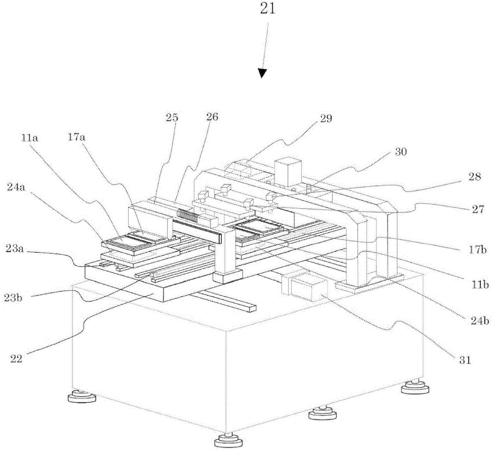
[0190] Next, for an embodiment of the bonding device of the substrate of the present invention, refer to image 3 and Figure 4 illustrate. image 3 It is an external view showing a schematic configuration of an embodiment of the substrate bonding apparatus of the present invention. again, Figure 4 It is an explanatory diagram showing a planar arrangement of each functional unit constituting the substrate bonding apparatus of the present invention. The outline of the device of the present invention will be described using these two figures.

[0191] Such as image 3 It shows that the laminating device 21 of the substrate is equipped with a moving shaft 23a and a moving shaft 23b for laying two substrates that can be moved by a ball screw on a base 22 that can move back and forth, and is equipped with two moving shafts that can be positioned separately. The three-degree-of-freedom actuator on the moving shafts 23a and 23b is a substrate transfer system (each functional co...

Embodiment 2

[0235] As mentioned above, although the purpose of pre-curing is to prevent leakage or insufficient flow diffusion during bonding, once the viscosity-controlled bonding material is used in the bonding process, there is a possibility of omitting the pre-curing process. Especially when the viscosity of the material is about one digit higher than that of the current main materials (for example, around 50000cps), the flow can also be suppressed, and the experimental results that the coating shape can also be formed more stably can be obtained. Although the above high-viscosity bonding materials cannot be implemented with a slit-type coater that can stably and intermittently coat high-viscosity materials in a coating process that is more difficult than a bonding process, recently, a spiral quantitative material supply pump 37 The use of a coating head (slot-type coating head 34) that can withstand high pressure can be realized.

[0236] In the case where the pre-curing process can ...

Embodiment 3

[0239] also available from image 3 and Figure 4 It is known that the processes on the outer moving shaft 23a and the moving shaft 23a' are completely the same (coating function and pre-curing function). And, when these functions are performed differently from the outside of the left and right, it is natural that these functional components move and act alternately at the positions of the movement shaft 23a and the movement shaft 23a'. As long as the accuracy can be guaranteed, the slit-type coating head 34 and the ultraviolet irradiation head 38 can be formed into a single high-precision device, and the Figure 4 ( Figure 9 ) The process conditions and control calculations of state A and state B form a single, that is, it is possible to respond with a simplified control method.

[0240] In addition, the price can also be reduced from two units to one unit, which has the advantage of significantly reducing the price. Specific as Figure 11 It shows that the structure of...


PUM


Abstract

The present invention aims to provide a laminating device which consists of four functional elements respectively for coating, precuring, aligning and laminating and achieves improvement of productbility, shortening of processing time, and great reduction of set area of a device on the premise of ensuring quality in the laminating process of laminating a plurality of devices such as smart phones or flat terminals through optical resin. The laminating device of substrate is characterized in that two independent left and right shafts arranged in a direction perpendicular to the moving direction of a base are respectively carried on the base capable of moving back and forth, through two substrate loading platforms capable of moving along the left and right shafts and capable of positioning, the base moves back and forth, thereby ensuring three independent moving shaft positions, on the three independent moving shaft positions, the functional elements respectively for coating, precuring, aligning and laminating are provided for performing laminating of two substrates with carrying of the substrates.

Description

technical field [0001] The present invention relates to the composition and arrangement of a substrate bonding device and its method, covering the process of vacuum bonding a display substrate mounted with a display module such as liquid crystal or organic EL and a protective substrate such as a touch sensor or cover glass. Background technique [0002] An intelligent terminal device represented by a smart phone or a tablet terminal is a composite terminal device that integrates a display device such as a touch sensor of an input device and a liquid crystal display, and adds computing functions and communication functions. The smart terminal device has a display device on the bottom layer, an input device on the upper layer, and a protective glass on the top layer. By compounding and combining these various functions into a smart terminal device, a laminating device is used for joining each component. [0003] Display devices or liquid crystal displays are the most common d...

Claims


Application Information

Patent Timeline
IPC IPC(8): B32B37/00B05D3/06
Inventor 渡边道弘齐藤忠之田岛淳一中村登
Owner TELECOMM SA
Why Eureka
Try Eureka