Reduction furnace operation control method

A technology of operation control and reduction furnace, which is applied in the direction of temperature control by electric means, chemical instruments and methods, auxiliary controller with auxiliary heating device, etc., can solve the problem of uneven distribution of heat field and gas field of large reduction furnace, Achieve the effect of increasing the yield of disposable materials, improving product quality and reducing production costs

Active Publication Date: 2015-08-26
XINTE ENERGY
View PDF3 Cites 6 Cited by
  • Summary
  • Abstract
  • Description
  • Claims
  • Application Information

AI Technical Summary

Problems solved by technology

[0006] Aiming at the above-mentioned deficiencies in the prior art, the present invention provides a reduction furnace operation control method to solve the problem of uneven distribution of heat field and gas field in a large reduction furnace with 48 pairs of rods

Method used


Image

  • Reduction furnace operation control method
  • Reduction furnace operation control method

Examples


Embodiment 1

[0069] Embodiment 1 is the case where the tail gas hole is located in the middle of the bottom plate of the reduction furnace. 48 pairs of silicon rods are divided into 4 layers and arranged on the chassis of the reduction furnace, and the silicon rods of each layer are distributed concentrically with the exhaust holes.

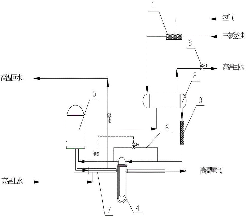
[0070] The initial pressure in the reduction furnace 5 is set to 0.55MPa, and the initial temperature is set to 1120-1150°C. The initial flow rate of hydrogen is 15-25kg / h, during feeding process, open trichlorosilane regulating valve gradually, make trichlorosilane and hydrogen carry out heat energy exchange in feed preheater 2 with hydrogen, obtain The mixed gas of trichlorosilane and hydrogen is transported to the reduction furnace 5 through the tail gas heat exchanger 4, so as to feed the reduction furnace 5.

[0071] When the mixed gas is initially delivered to the reduction furnace 5, the molar ratio of the mixed gas of hydrogen and trichlorosilane is ...

Embodiment 2

[0081] Example 2 is the case where the tail gas holes are evenly distributed on the outside of the bottom plate of the reduction furnace (at the circumference of the bottom plate). 48 pairs of silicon rods are set on the reduction furnace chassis, and 3-6 pairs of silicon rods in the middle of the reduction furnace chassis are used as the core circle (that is, the first layer of silicon rods), and the rest of the silicon rods are divided into 3 layers (2-4 layers Silicon rods), each layer of silicon rods is concentrically distributed with the core circle.

[0082] The operation control process of the reduction furnace in embodiment 2 is the same as that of embodiment 1, and will not be repeated here. The difference between embodiment 2 and embodiment 1 is that the control process of applying different current intensities to the silicon rods of each layer by using phase-splitting current is different. In embodiment 2, the control process of applying different current intensitie...


PUM


Abstract

The invention provides a reduction furnace operation control method. The method comprises setting initial pressure in a range of 0.45-0.6MPa in a reduction furnace, setting an initial temperature in a range of 1120-1150 DEG C, continuously feeding trichlorosilane and hydrogen to form mixed gas, continuously conveying the mixed gas into the reduction furnace in reduction furnace operation, carrying out a continuous reaction process on the mixed gas in the reduction furnace, controlling a reduction furnace temperature in a range of 900-1100 DEG C in 0-5h after conveying of the mixed gas into the reduction furnace, when the mixed gas undergoes a reaction in the reduction furnace for 30-60h, according to distribution of a hot field and a gas field in the reduction furnace, applying different intensity of currents for all layers of silicon rods in the reduction furnace at time intervals so that equalization of the hot field and the gas field in the reduction furnace are kept, and keeping a reduction furnace temperature in a range of 900-1100 DEG C until the reduction furnace is stopped.

Description

technical field [0001] The invention relates to the technical field of polysilicon reduction, in particular to a polysilicon production [0002] A reduction furnace operation control method in the process. Background technique [0003] At present, in the polysilicon production process, the largest reduction furnace operating at home and abroad is 36 pairs of rods. In the existing 36 pairs of rod reduction furnace operation control process, affected by the gas field in the furnace, the temperature of the silicon rods near the tail gas hole is higher , resulting in unbalanced distribution of heat field and gas field in the furnace, and uneven distribution of heat field and gas field directly restricts the normal operation of the reduction furnace, leading to atomization, making the environment in the reduction furnace turbid, producing fine silicon powder, and easy to turn down the furnace. The produced silicon powder brings many adverse effects to the reduction furnace syste...

Claims


Application Information

Patent Timeline
Patent Type & Authority Applications(China)
IPC IPC(8): C01B33/035G05D23/30
Inventor 梁国东王文邹分红梁立刚其他发明人请求不公开姓名
Owner XINTE ENERGY
Why Eureka
Try Eureka