Flat heat pipe liquid suction core provided with fins and embedded grooves and manufacturing method thereof

A technology of a flat heat pipe and a manufacturing method, which is applied to indirect heat exchangers, lighting and heating equipment, etc., can solve the problems of uncontrollable groove-hole structure shape, poor boiling heat transfer performance, small capillary radius, etc., and achieve improved boiling Effects of heat transfer performance, reduction of penetration resistance, and reduction of capillary radius

CN104864755AInactive Publication Date: 2015-08-26XIAMEN UNIV
4 Cites 13 Cited by

Patent Information

Authority / Receiving Office
CN · China
Patent Type
Applications(China)
Current Assignee / Owner
Publication Date
2015-08-26
Estimated Expiration
Not applicable · inactive patent

Smart Images

  • Figure 1
    Figure 1
  • Figure 2
    Figure 2
  • Figure 3
    Figure 3
Patent Text Reader

Abstract

The invention discloses a flat heat pipe liquid suction core provided with fins and embedded grooves and a manufacturing method thereof. The flat heat pipe liquid suction core comprises a metal evaporation plate, wherein multiple first embedded grooves and multiple second embedded grooves which are arranged at intervals and distributed in a staggered mode in the first direction and the second direction and multiple fins distributed in an array mode are arranged on the evaporation face of the metal evaporation plate, and each first embedded groove and each second embedded groove respectively comprises a groove body forming a groove cavity and a vertical gap forming a groove opening. Each fin comprises a fin body and a supporting boss and is formed by the gaps and internal groove bodies of the corresponding first embedded groove and the corresponding second embedded groove in a staggered mode. The liquid suction core can increase heat exchange area, promote boiling for nucleus formation, enhance boiling heat transfer, improve capillary pressure and reduce backflow resistance. During manufacture, a ball-end milling cutter is utilized to mill the embedded grooves in the first direction, and a base plate is turned to mill the embedded grooves in the second direction and meanwhile form a fin structure. The flat heat pipe liquid suction core is simple in manufacturing process and low in machining cost and can remarkably strengthen heat transfer.
Need to check novelty before this filing date? Find Prior Art

Description

technical field

[0001] The invention relates to a flat heat pipe liquid-absorbing core, in particular to a flat heat pipe liquid-absorbing core with a fin-embedded groove and a manufacturing method thereof. Background technique

[0002] As the power of electronic chips continues to increase and the physical size continues to decrease, the heat flux on the electronic chip continues to increase. The problem of thermal failure of electronic chips due to excessive temperature is becoming more and more serious. The heat dissipation problem of high heat flux components It has become one of the key technical issues affecting the design of electronic devices.

[0003] At present, many heat dissipation devices are far from meeting the heat dissipation requirements of some electronic devices, and traditional heat dissipation methods such as air cooling have reached a technical bottleneck. The flat heat pipe utilizes the principle of phase change heat transfer. Because it adopts the s...

Examples

Embodiment Construction

[0031] The present invention will be further described in detail below with reference to the accompanying drawings and examples; however, the flat heat pipe wick with fins and embedded grooves and its manufacturing method of the present invention are not limited to the examples.

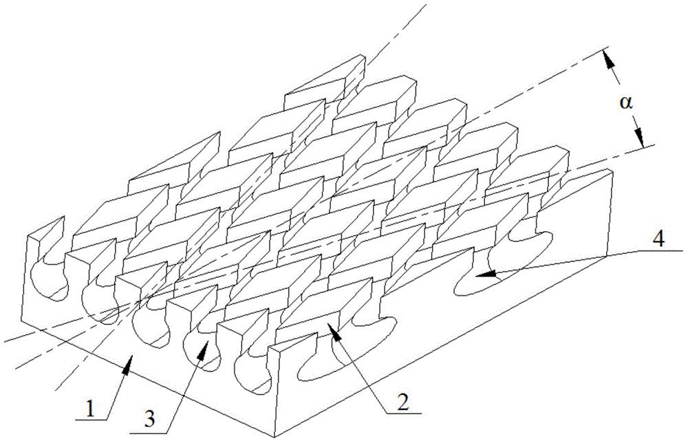
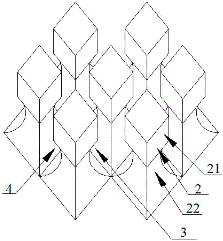
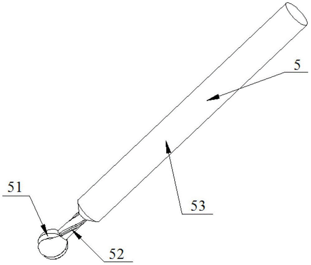
[0032] Examples, see Figure 1-Figure 3 As shown, a flat heat pipe liquid-absorbing wick with fins-embedded grooves of the present invention includes a metal evaporation plate 1, and the evaporation surface of the evaporation plate 1 is provided with a plurality of parallel intervals along the first direction. The first embedded groove 3, a plurality of second embedded grooves 4 arranged in parallel and at intervals along the second direction, and a plurality of fins 2 distributed in an array; the first embedded groove 3 and the second embedded groove 4 One by one intertwined. The first embedded groove 3 and the second embedded groove 4 respectively comprise upper and lower parts, the upper part is ...