
Three-directional shearing model box device

A technology for shearing model boxes and rubber molds, which can be used in measurement devices, vibration testing, and testing of machine/structural components. Easy installation and application, simple construction, low mass effect

Inactive Publication Date: 2015-08-26
BEIJING UNIV OF TECH
View PDF5 Cites 8 Cited by
  • Summary
  • Abstract
  • Description
  • Claims
  • Application Information

AI Technical Summary

Problems solved by technology

[0002] The soil-structure dynamic interaction needs to be considered in the non-bedrock nuclear power plant model shaking table test, so there must be a container for holding the soil-shear model box, because the shear model box can eliminate boundary effects, and the main structure of the nuclear power plant belongs to Type I items must consider the multi-layer vertical horizontal direction and the response under a vertical earthquake action. The connection between the traditional layered model boxes can only be in the multi-layer vertical horizontal direction or a single horizontal direction. movement, the shear model box cannot move freely in three directions when the three-dimensional seismic excitation is input, thus affecting the vibration characteristics of the model soil; in addition, most of the traditional layered model boxes are rectangular or square, and when the input When the earthquake is excited, in order to prevent its displacement from being too large, it is necessary to protect the end of the box or install a limit device. Not only is the cost high, but the installation is also difficult, and it is difficult to meet the model with high hardness of the soil and large lateral displacement. Test requirements

Method used


Image

  • Three-directional shearing model box device
  • Three-directional shearing model box device
  • Three-directional shearing model box device

Examples


Embodiment Construction

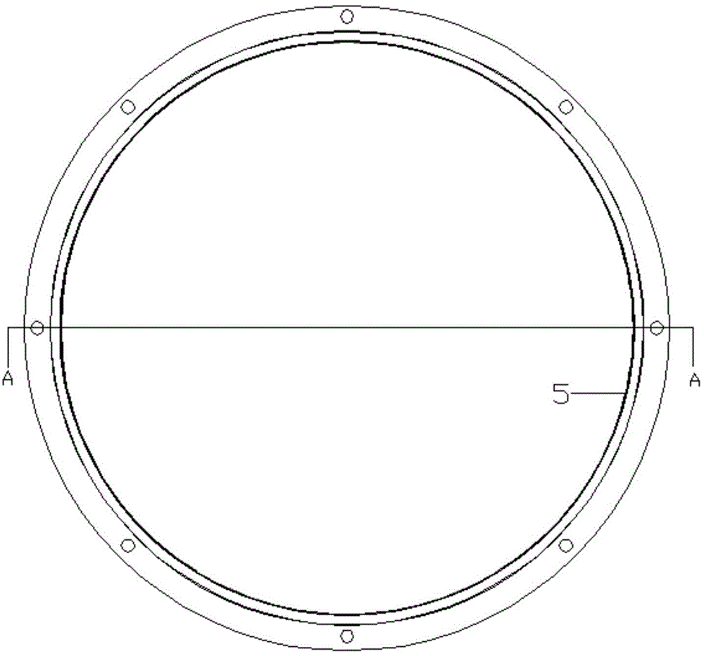
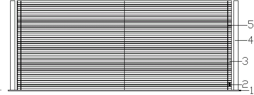
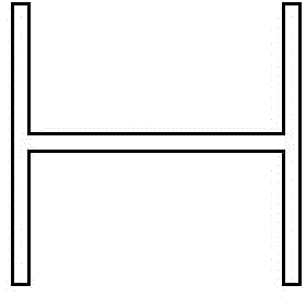
[0021] Such as Figure 1-3 As shown, a three-way shear model box device according to an embodiment of the present invention includes: a steel plate, a plurality of frame layers, which are installed on the upper part of the steel plate 1; the frame layer includes: a multilayer frame 3, rubber Die 5, which is riveted on the inside of the frame 3; Support 2, which is installed between the frame 3 layers of the column 4, which is installed on the periphery of the steel plate 1; The frames 3 are arranged vertically and equidistantly in parallel The frame 3 is a circular closed aluminum alloy H-shaped steel, the upper part of the support 2 has the same structure as the lower part, and the support 2 and the uprights 4 are arranged at equal intervals. In the shear model box, the steel plate 1 should have sufficient bearing capacity to ensure safety during the hoisting process; the frame 3 is aluminum alloy H-shaped steel, and the aluminum alloy H-shaped steel is welded by argon arc to ...


PUM


Abstract

The invention discloses a three-directional shearing model box device. The device comprises a steel plate and multiple framework layers mounted above the steel plate. The framework layers comprise multiple layers of frameworks, rubber dies arranged on the inner sides of the frameworks in a riveting manner, supporting units mounted between the framework layers, and columns mounted on the periphery of the steel plate. The frameworks are made of light aluminum alloy materials. The frameworks are parallelly arranged at equal vertical intervals. The columns are arranged on the periphery of a shearing model box at equal intervals, so that the shearing model box can freely move in three directions when inputting three-directional seismic excitation, and ultra-displacement, jumping and shedding phenomena during a test of the shearing model box can be avoided. The frameworks are made of aluminum alloy H-section steel, so that the weight of the shearing model box is reduced, and the influence on the whole model by the framework weight can be reduced. The aluminum alloy H-section steel frameworks have enough rigidity, so that the model soil is zero in lateral strain in the horizontal direction, and the aluminum alloy H-section steel frameworks can maintain original states after the seismic motion excitation.

Description

Technical field [0001] The invention belongs to the technical field of civil engineering, and relates to a three-way shear model box device used for the shaking table test of a non-base rock nuclear power plant structure. Background technique [0002] It is necessary to consider the dynamic interaction of soil-structure in the shaking table test of non-bedrock nuclear power plant model. Therefore, a container-shear model box containing soil must be provided, because the shear model box can eliminate the boundary effect. The main structure of the nuclear power plant belongs to Class I items must consider the response of multiple layers of mutually perpendicular horizontal directions and a vertical earthquake. The connection between the layers of the traditional layered model box can only be in the horizontal direction or a single horizontal direction. Moving, the shear model box cannot move freely in three directions when the three-way seismic excitation is input, thereby affectin...

Claims


Application Information

Patent Timeline
IPC IPC(8): G01M7/02
Inventor 李小军王晓辉李亮王贵英
Owner BEIJING UNIV OF TECH
Learn More