Fault detection circuit and method for detecting circuit failure by using fault detection circuit
A fault detection circuit and fault technology, applied in electronic circuit testing, circuit devices, emergency protection circuit devices, etc., can solve problems such as failure to detect electronic device faults, and achieve the effect of simple structure and low cost
- Summary
- Abstract
- Description
- Claims
- Application Information
AI Technical Summary
Problems solved by technology
Method used
Image

Examples
no. 1 example
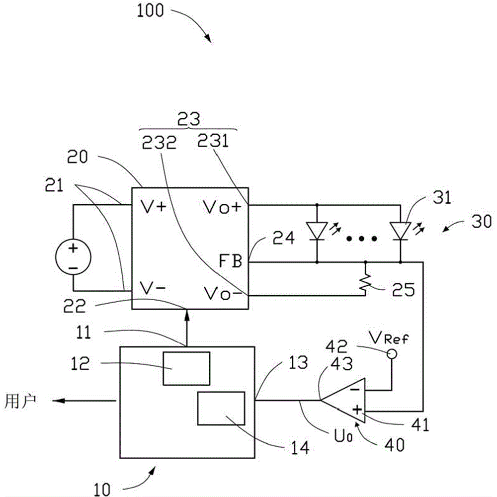
[0020] See figure 1 , the fault detection circuit 100 of the first embodiment of the present invention includes a microprocessor 10, a driver 20 connected to the microprocessor 10, a load 30 driven by the driver 20, and a load 30 connected to the microprocessor 10 Comparator 40 between.
[0021] The microprocessor 10 includes at least one output terminal 11 , at least one input terminal 13 , a PWM (Pulse Width Modulation) module 12 and a detection module 14 inside the microprocessor 10 .
[0022] The PWM module 12 outputs a first pulse sequence signal from the output terminal 11 of the microprocessor 10 to trigger the driver 20 to drive the load 30 to work. In this embodiment, the PWM module 12 outputs the first pulse sequence signal to trigger the driver 20 to output the second pulse sequence signal.
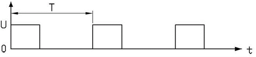
[0023] The first pulse sequence signal output by the PWM module 12 is a square wave sequence signal with a volt value of U and a period of T (such as figure 2 ). The duty ...
no. 2 example
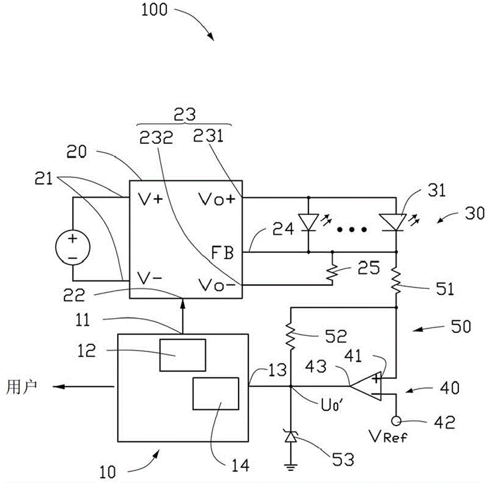
[0036] See image 3 , the comparator 40 also includes an anti-jamming circuit module 50 . The anti-jamming circuit module 50 includes a first resistor 51 , a second resistor 52 and a Zener diode 53 .
[0037] One end of the first resistor 51 is connected to the negative pole of the load 30 , and the other end of the first resistor 51 is connected to the non-inverting input end 41 of the comparator 40 . One end of the second resistor 52 is connected to the other end (non-inverting input end 41 ) of the first resistor 51 , and the other end of the second resistor 52 is connected to the output end 43 of the comparator 40 . The anode of the Zener diode 53 is connected to a ground terminal, and the cathode of the Zener diode 53 is connected to the output terminal 43 of the comparator 40 .
[0038] Figure 4 The second sequence signal U taken out from the output terminal 43 of the comparator 40 in the first embodiment is shown in 0 And the second sequence signal U taken out from...
PUM
 Abstract
Description
Claims
Application Information
 - R&D
- Intellectual Property
- Life Sciences
- Materials
- Tech Scout
- Unparalleled Data Quality
- Higher Quality Content
- 60% Fewer Hallucinations
Browse by: Latest US Patents, China's latest patents, Technical Efficacy Thesaurus, Application Domain, Technology Topic, Popular Technical Reports.
© 2025 PatSnap. All rights reserved.Legal|Privacy policy|Modern Slavery Act Transparency Statement|Sitemap|About US| Contact US: help@patsnap.com