
Alpha and beta ray detector

A detector, beta-ray technology, applied in radiation measurement, X/γ/cosmic radiation measurement, instruments, etc., can solve problems such as the reduction of the effective detection area of ​​the detector, the difficulty of re-opening the detector, the destruction of the film and the shell, etc. , to achieve the effect of increasing the effective detection area, reducing the "dead zone" area, and shortening the assembly cycle.

Active Publication Date: 2015-08-26
中国人民解放军63973部队
View PDF5 Cites 7 Cited by
  • Summary
  • Abstract
  • Description
  • Claims
  • Application Information

AI Technical Summary

Problems solved by technology

[0006] In the past detectors, the thin plastic scintillator, light-shielding film, detector housing, and protective cover are in hard contact. In order to achieve the ideal light-shielding effect, black liquid silicone is used to protect the contact edges of these four during assembly. It is difficult to open the detector again, which is not conducive to on-site maintenance. At the same time, the film and shell are also damaged, which is difficult to recycle and reuse, resulting in waste
[0007] In the past, the protective cover grid of the detector used a thin metal plate with several square holes, and its own ray transmittance could not be made very high (<60%) due to the limitation of the punching process, so that the effective detection area of ​​the detector was greatly increased. reduce

Method used


Image

  • Alpha and beta ray detector
  • Alpha and beta ray detector
  • Alpha and beta ray detector

Examples


example 1

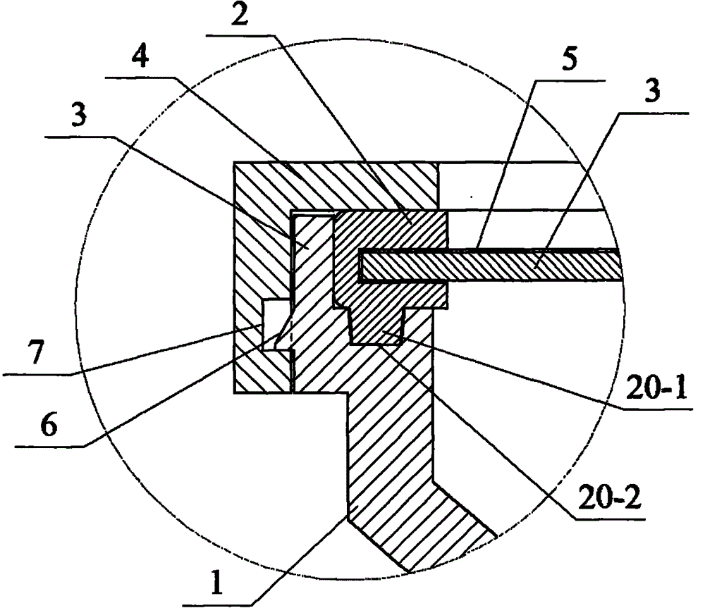
[0040] figure 1 with figure 2 Describes how to design the detection window of the detector casing 1 to avoid light. The detection window is rectangular, and there is a notch 18 on the side wall, and a flicker light shielding assembly 19 is placed inside the notch 18, and the protective cover 4 is buckled outside the notch 18. The scintillation light-shielding assembly 19 includes a thin plastic scintillator 3, a light-shielding film 5, and a black silicone ring 2; three layers of light-shielding film 5 are used to wrap the outer surface, side circumference and inner surface edge of the thin plastic scintillator 3. The black silicone ring 2 is rectangular, formed by mold injection molding process, has a certain degree of elasticity, the total length is slightly smaller than the circumference of the sheet plastic scintillator 3, and the cross-section is C-shaped, using the C-shaped opening and the elasticity of the black silicone ring 2 to wrap the wrapped to avoid light Shee...

example 2

[0049] The detection window can also be designed as a circle, a square or other shapes that are easy to detect.

[0050] The test results of the principle prototype designed according to the present invention prove that the α and β ray detectors have simple structure, short assembly cycle, high reliability, good maintainability, suitable for on-site maintenance and large effective detection area by adopting the technical scheme of the present invention.


PUM


Abstract

The present invention relates to a ray detector and particularly relates to an alpha and beta ray detector with the form of the combination of a thin plastic scintillator and a photomultiplier tube. Through the structural design, external photons are avoided from entering into the detector as far as possible, the inner surface light collection efficiency of the detector is improved, and the ray transmission area of a detection window is increased. The light shielding of the detection window is mainly rely on the elastic contact of a black silicone ring with the plastic scintillator, a light shielding film, a shell side wall and a protection cover. The inner surface of a detector shell is coated with an aluminium film, thus the flashing light reflection factor is larger than 0.9, the four walls of the detector shell are designed to be slopes, the reflection times of the flashing light in the detector shell is reduced, and thus the photons can be gathered quickly. The shield grids of the detection window have two forms, one is a honeycomb hexagonal grid, the transmittance of ray vertical incidence is larger than 90%, the other one is the combination of a hexagonal grid with a stainless steel gauze, and the transmittance of the ray vertical incidence is larger than 75%. The detector has the advantages of simple structure, high maintainability and high detection efficiency.

Description

technical field [0001] The invention relates to an α and β ray detector, in particular to an α and β ray detector in the form of a combination of a thin plastic scintillator and a photomultiplier tube. Background technique [0002] The α and β ray detectors are sensors for personnel's whole body α and β pollution monitors, hand and foot α and β pollution monitors, etc., which can quickly detect the α and β rays contaminated on the surface of the human body to determine whether the personnel are radioactively polluted . It is mainly used in personal pollution monitoring in nuclear power plants, nuclear processing plants, nuclear warehouses and other radioactive workplaces. [0003] The principle of α and β-ray detectors in the form of a combination of thin plastic scintillators and photomultiplier tubes is: when the rays enter the thin scintillator, the atoms or molecules of the scintillator are ionized or excited, and when de-excitation, part of the ionization or excitation...

Claims


Application Information

Patent Timeline
Patent Type & Authority Applications(China)
IPC IPC(8): G01T1/203G01T7/00
Inventor 曹保锋宋立军肇文丽刘伟王尊刚范江兵李英男李欣赵洪伟
Owner 中国人民解放军63973部队
Learn More