
Electrical switching device with a triple motion contact arrangement

A technology of contacts and contact sets, applied in electrical switches, high-voltage/high-current switches, circuits, etc., can solve problems such as reduced life time, increased mechanical stress, and dielectric failure.

Active Publication Date: 2015-08-26
HITACHI ENERGY LTD
View PDF9 Cites 7 Cited by
  • Summary
  • Abstract
  • Description
  • Claims
  • Application Information

AI Technical Summary

Problems solved by technology

These forces can lead to increased mechanical stress on the moving parts of the contact arrangement and even lead to mechanical failure, reducing the life time of such electrical switching devices
Furthermore, particles are generated during the switching process of the circuit breaker, which can lead to dielectric failure

Method used


Image

  • Electrical switching device with a triple motion contact arrangement
  • Electrical switching device with a triple motion contact arrangement
  • Electrical switching device with a triple motion contact arrangement

Examples


Embodiment Construction

[0034] The invention is described for the example of a high-voltage circuit breaker, but the principle described below also applies to the use of the invention in other switching devices, for example of the type mentioned at the outset.

[0035] In the following, the same reference numerals indicate structurally or functionally identical or similar elements of various embodiments of the present invention.

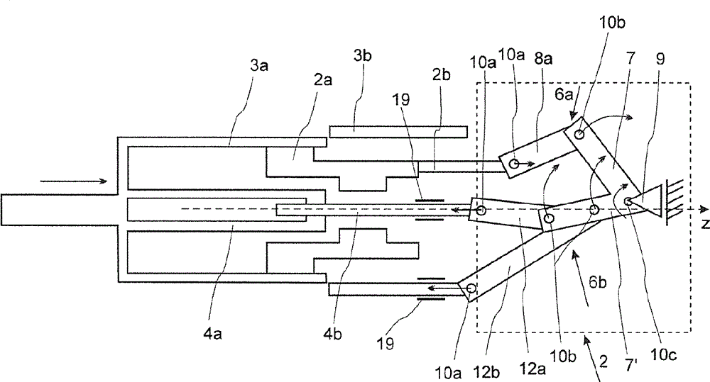
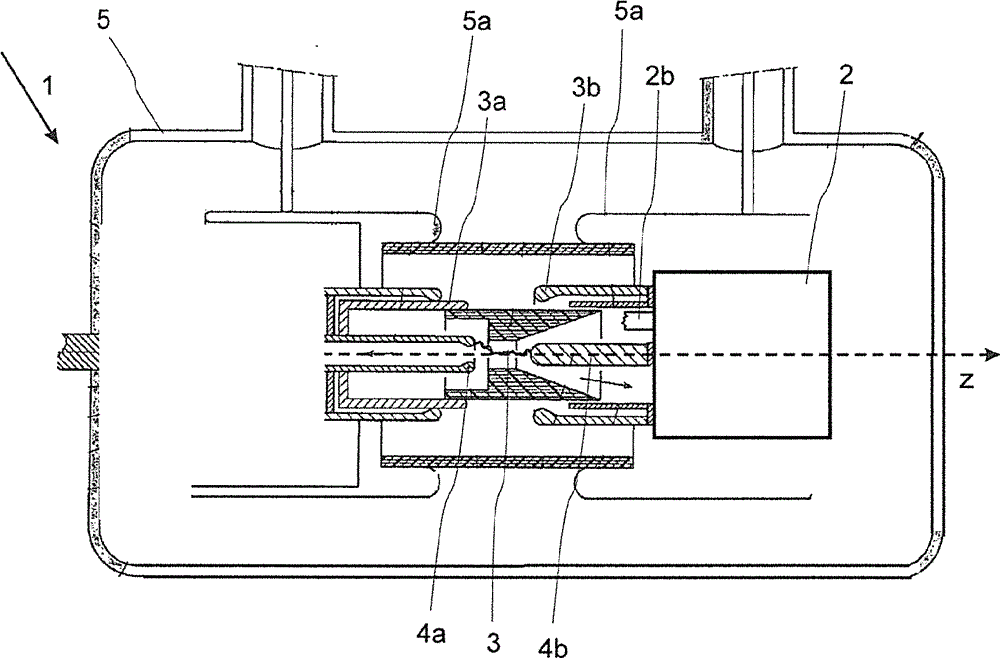
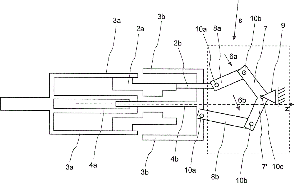
[0036] figure 1 A cross-sectional side view of an exemplary embodiment of a high-voltage circuit breaker 1 with a mechanical coupling 2 is shown exemplarily during a disconnection process. The circuit breaker 1 without mechanical coupling 2 is rotationally symmetrical about the longitudinal axis z. Only the elements of the circuit breaker 1 which are relevant to the invention will be described below, other elements present in the figures are not relevant for understanding the invention and are known to those skilled in high voltage electrical engineering. The first contac...


PUM


Abstract

A contact arrangement has a longitudinal axis (z) with a first contact group having a first contact and a second contact, and a second contact group having a third contact and a fourth contact. The first contact interacts electrically and mechanically with the third contact, and / or the second contact interacts electrically and mechanically with the fourth contact. At least one mechanical coupling is provided for transmitting an actuation force to the second contact group and thereby moving the second contact group. The third and the fourth contact can move in such a way that their speeds differ along at least a portion of a travel path of the third contact or of the fourth contact.

Description

technical field [0001] The present invention relates to the field of medium and high voltage switchgear technology and to a contact arrangement according to the independent claims and to an electrical switching device with such a contact arrangement, in particular for use in power transmission and distribution systems as an earthing device, a fast-acting earthing device, Circuit breakers, generator circuit breakers, switch isolators, combination isolators and earthing switches or load break switches. Background technique [0002] Electrical switchgear is well known in the field of medium and high voltage switching applications. They are used, for example, to interrupt the current flow in the event of an electrical fault. As an example for electrical switching devices, a circuit breaker has the task of breaking the contacts and keeping them away from each other in order to avoid current flow, even in the case of high potentials originating from the electrical fault itself. ...

Claims


Application Information

Patent Timeline
Patent Type & Authority Applications(China)
IPC IPC(8): H01H33/90H01H33/91
CPCH01H33/91H01H3/00H01H33/904H01H3/46H01H33/64
Inventor H.海尔梅尔J.科斯托维J.科贝R.卡雷S.科蒂莱恩T.苏特兰德B.苏里伊
Owner HITACHI ENERGY LTD
Features
  • Generate Ideas
  • Intellectual Property
  • Life Sciences
  • Materials
  • Tech Scout
  • Unparalleled Data Quality
  • Higher Quality Content
  • 60% Fewer Hallucinations
Learn More