Device for treating coal dust during coal transportation for coal-fired power plant

A technology for coal-fired power plants and treatment devices, applied in separation methods, filtration separation, and dispersed particle separation, etc., can solve problems such as frequent failures, large water consumption, and increased operating resistance, and achieve maintenance-free emissions, reliable operation, and maintenance simple effect

Inactive Publication Date: 2015-09-02
WUHAN UNIV
View PDF5 Cites 0 Cited by
  • Summary
  • Abstract
  • Description
  • Claims
  • Application Information

AI Technical Summary

Problems solved by technology

[0004] The structure of the water-bath impulse dust collector is simple, but the fan power is large (30-40KW), the water consumption is large (1.2-1.5t / h), and the noise is large; the dust removal efficiency of the electrostatic precipitator is high, but it is affected by the resistivity of coal dust. Coal dust has a certain selectivity. For example, the humidity of coal dust is high, the polar plate is damp and ash accumulates, the discharge performance is greatly reduced, condensation and creepage are formed on the edge, and the operation trips, so that the actual input rate of electrostatic precipitator is very low; After the bag is wet, the running resistance increases, the bag is clogged, it is difficult to clean the dust, frequent failures, and cannot continue to run for a long time; the cyclone dust collector has a limited ability to capture coal dust due to the centrifugal force, and the dust removal efficiency is not high
Therefore, the investment rate of these dust collectors is less than 50%, and the operation effect is not good;
[0005] At present, there is no dust removal method for coal-fired power plants that uses the wind tunnel effect to construct a water recycling, low noise, reliable operation, safe use, low cost, simple maintenance, and no emissions.

Method used


Image

  • Device for treating coal dust during coal transportation for coal-fired power plant

Examples


Embodiment Construction

[0013] In order to facilitate those of ordinary skill in the art to understand and implement the present invention, the present invention will be described in further detail below in conjunction with the accompanying drawings and embodiments. It should be understood that the implementation examples described here are only used to illustrate and explain the present invention, and are not intended to limit this invention.

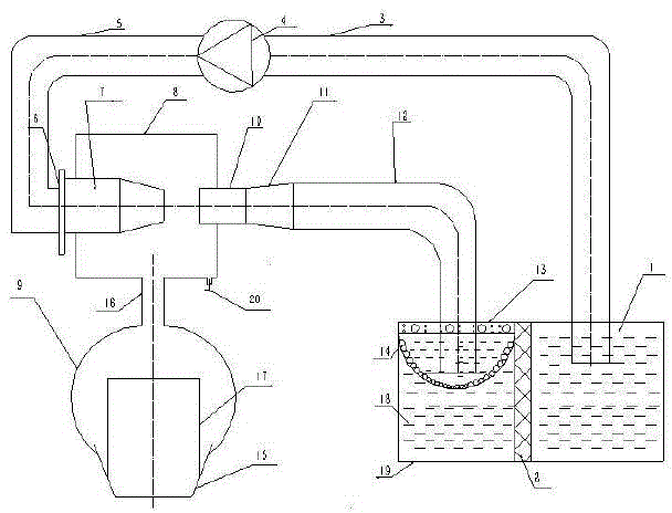
[0014] please see figure 1 , a kind of coal dust treatment device for coal transportation in a coal-fired power plant provided by the present invention, comprising a water supply chamber 1, a pump inlet pipe 3, a low-pressure water supply pump 4, a pump outlet pipe 5, a multiphase fluid vacuum dust removal chamber, and a dust collection hood 9. Diffusion pipe 11, coal dust slurry outlet pipe 12, coal dust filtration and precipitation chamber; multiphase fluid vacuum dust removal chamber includes water inlet nozzle 7, coal dust inlet 16, multiphase fluid vacuu...


PUM


Abstract

The invention discloses a device for treating coal dust during coal transportation for a coal-fired power plant. The device comprises a water supply chamber, a pump water inlet pipeline, a low-pressure water supply pump, a pump water outlet pipeline, a multi-phase fluid vacuum dust removal chamber, a dust suction hood, a coal dust slurry water outlet pipe, a coal dust filtering and sedimentation chamber; according to the invention, through the utilization of the wind tunnel effect of fluid mechanics, and under the circumstance that water supply potential energy of the pipeline is not changed, interconversion between kinetic energy and pressure energy is realized through the change of structure sizes of the inlet and the outlet of the multi-phase fluid dust removal chamber and the pipeline section thereof, and the pressure change of the vacuum degree of the dust removal chamber as well as orifices and pipelines thereof is formed, so that automatic mixing of air, water and coal dust in the dust removal chamber is realized, and the mixture is conveyed to the coal dust filtering and sedimentation chamber; a traditional suction method that a motor drives a fan is replaced and generated multiple-phase fluid circulates in a closed system, so that recycling of water is realized, the noise is low, running is reliable, the using is safe, the low is low, the maintenance is simple and zero emission of coal dust is realized.

Description

technical field [0001] The invention belongs to the technical field of thermal power generation, and relates to a coal dust treatment device for a coal-fired power plant, in particular to a coal dust treatment device for transporting coal in a coal-fired power plant. Background technique [0002] During the transportation of coal in coal-fired power plants, a large amount of coal dust is generated due to the drop in transfer, which not only damages the health of workers, but also causes malfunctions in the control system after coal dust enters electrical components, and even causes explosions and spontaneous combustion. [0003] Coal dust treatment methods commonly used in coal handling systems at home and abroad include: water bath impulse dust collector, electrostatic precipitator, bag filter, cyclone dust collector, etc. [0004] The structure of the water-bath impulse dust collector is simple, but the fan power is large (30-40KW), the water consumption is large (1.2-1....

Claims


Application Information

Patent Timeline
Patent Type & Authority Applications(China)
IPC IPC(8): B01D47/06B01D36/04
Inventor 宋凤莲谢炎柏
Owner WUHAN UNIV
Why Eureka
Try Eureka