Automatic oil tank water draining method

An oil tank and automatic technology, which is applied in the field of automatic water cutting of oil tanks, can solve the problems of high manual operation intensity, low safety factor and high oil content in drainage, so as to reduce oil waste and environmental pollution, overcome major safety hazards, reduce The effect of labor intensity

Inactive Publication Date: 2015-09-02
CHINA PETROLEUM & CHEM CORP +1
View PDF5 Cites 8 Cited by
  • Summary
  • Abstract
  • Description
  • Claims
  • Application Information

AI Technical Summary

Problems solved by technology

[0005] The technical problem to be solved by the present invention is that in the prior art, the intensity of manual operation is high, the separation of oil and water cannot be strictly controlled, the oil content of drainage is relatively high, the environment is polluted, and the safety factor is low. water cutting method

Method used


Image

  • Automatic oil tank water draining method

Examples


Embodiment 1

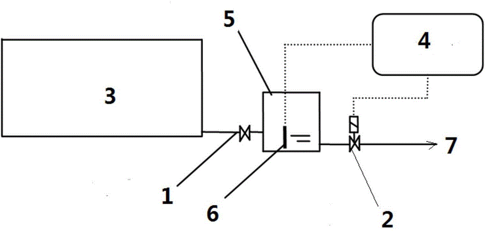
[0014] In the water cutting operation of an oil storage tank A, the water produced in the oil tank enters the water cutting tank through valve 1. The original water level of the water cutting tank is 40cm high. As the water in the oil tank gradually flows into the water cutting tank, the water level rises to 60cm. The oil-water interface monitoring sensor detects that the thickness of the oil film is 0.025-0.03mm, and sends a signal to the controller. The controller switches the solenoid valve 2 remotely to discharge the water in the water cutting tank. No obvious oil blooms can be seen in the water, and the water is cut into the sewage treatment system. , When the water level in the water cutting tank drops to 45cm, the solenoid valve 2 is closed, and the water cutting ends.

Embodiment 2

[0016] In the water cutting operation of an oil storage tank B, the water produced in the oil tank enters the water cutting tank through valve 1. The original water level of the cutting water tank is 80cm high. As the water in the oil tank gradually flows into the water cutting tank, the water level rises to 120cm, and the oil and water The interface monitoring sensor detects that the thickness of the oil film is 0.025-0.03mm, and sends a signal to the controller. The controller switches the solenoid valve 2 remotely to discharge the water in the water cutting tank from the bottom. No obvious oil blooms can be seen in the water, and the water is cut into the sewage treatment system, when the water level in the cutting water tank drops to 85cm, the solenoid valve 2 is closed.


PUM


Abstract

The invention relates to an automatic oil tank water draining method and aims to solve the problems of high manual operation strength, incapability of achieving strict control of oil-water separation, high oil content quantity of drained water, environmental pollution and low safety factor. According to the automatic oil tank water draining method, a pipeline is arranged at the bottom of at least one oil tank to be communicated with a water draining tank, an oil-water interface monitoring sensor is arranged in the water draining tank, an electromagnetic valve is arranged on a pipeline at an outlet of the water draining tank, and a controller is connected with the oil-water interface monitoring sensor and the electromagnetic valve through signal wires. When the water level in the water draining tank reaches or exceeds a set high limit value, the oil-water interface monitoring sensor sends a signal to the controller, the controller outputs a signal to the electromagnetic valve, the electromagnetic valve is turned on, and water in the water draining tank is drained out; When the water level in the water draining tank declines to the set high limit value, the electromagnetic valve is turned off and draining is terminated. The automatic oil tank water draining method solves the problems effectively and can be used or automatic oil tank water draining.

Description

technical field [0001] The invention relates to an automatic water cutting method for an oil tank. Background technique [0002] The rapid development of petroleum and petrochemical industry has higher and higher requirements for production technology and production automation. Low-level manual operation has greatly affected the improvement of comprehensive benefits of enterprises. Oil tank dehydration is a typical example. At present, the water cutting of oil tanks in the petrochemical industry is mostly manually operated, and the separation of oil and water cannot be strictly controlled, and the oil content of the drainage is relatively high, which not only causes waste of oil products, but also pollutes the environment; especially misoperations occur frequently, bringing significant safety hazard. [0003] At present, there are various water cutters for oil storage tanks. CN201310159117.X relates to an automatic water cutting system for an oil tank, including an oil tan...

Claims


Application Information

Patent Timeline
Patent Type & Authority Applications(China)
IPC IPC(8): B65D90/00
CPCB65D90/00
Inventor 周志国马传军房师平杨洋洋谢谚
Owner CHINA PETROLEUM & CHEM CORP
Why Eureka
Try Eureka