
Road drainage structure

A technology for drainage structures and roads, applied to drainage structures, roads, roads, etc., can solve the problems of not being able to play a better drainage role, the drainage effect cannot reach the ideal, and the drainage performance is not strong enough, so as to achieve the drainage performance and water permeability performance. Good, shortening the construction period, and the effect of strong flow conductivity

Inactive Publication Date: 2015-09-02
CHENGDU GERUISI CULTURAL COMM
View PDF10 Cites 3 Cited by
  • Summary
  • Abstract
  • Description
  • Claims
  • Application Information

AI Technical Summary

Problems solved by technology

[0002] Existing paved surfaces have a large area, such as roads, parking lots, bus stations, gas stations, sidewalks, etc. Most of these pavements require high drainage efficiency to avoid minimizing the wetness of the paved surface when rainwater accumulates, so Generally, paved roads are equipped with drainage channels. The drainage channels are usually covered by grille cover plates. U-shaped grooves or ditches of concrete or plastic materials are generally used to embed the drainage channels in the road surface, and the depth of the channels is also It is constantly deepening to adapt to the drainage intensity, but even so, the drainage effect still cannot reach the ideal state, the drainage performance is not strong enough, and it is easy to cause channel blockage due to debris, so that it cannot play a better drainage role

Method used


Image

  • Road drainage structure

Examples


Embodiment Construction

[0014] The present invention will now be described in further detail in conjunction with the accompanying drawings, which are simplified schematic diagrams, only schematically illustrating the basic structure of the present invention, and therefore only show the configurations related to the present invention.

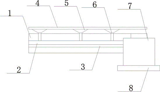
[0015] Such as figure 1 The preferred embodiment of the road drainage structure of the present invention shown includes a water-permeable formation 1, and a water-collecting member 5 is installed on the upper surface of the water-permeable formation 1. There is more than one water-collecting member 5, and it is a funnel-shaped structure. The top of the water-collecting member 5 is fixed on On the lower surface of a drainage formation 4, the drainage formation 4 is horizontally arranged on the water collection member 5, and the water guide member 6 is vertically arranged at the bottom of the water collection member 5 in the permeable formation 4, and the water guide memb...


PUM


Abstract

The invention discloses a road drainage structure which comprises a permeable ground layer. More than one water collecting component is mounted on the upper surface of the permeable ground layer and is of a funnel-shaped structure, the tops of the water collecting components are fixed onto the lower surface of a drainage ground layer, the drainage ground layer is transversely arranged on the water collecting components, water guide components are vertically arranged in the permeable ground layer, correspond to the bottoms of the water collecting components and are communicated with the water collecting components, a permeable layer made of permeable concrete is arranged on the lower surface of the permeable ground layer and is connected with the permeable ground layer by cement mortar layers, a medium-sand leveling layer is arranged in the permeable layer made of the permeable concrete, and the thickness of the medium-sand leveling layer is a quarter of the thickness of the permeable layer made of the permeable concrete. The road drainage structure has the advantages that the road drainage structure is excellent in drainage performance and permeation performance and high in flow guide property and can be effectively applied to municipal road drainage; drainage devices can be prefabricated, accordingly, the construction periods can be effectively shortened, the labor intensity can be relieved, certain costs can be saved, and destruction to the bearing capacity of roads can be prevented.

Description

technical field [0001] The invention relates to a drainage structure, in particular to a road drainage structure. Background technique [0002] Existing paved surfaces have a large area, such as roads, parking lots, bus stations, gas stations, sidewalks, etc. Most of these pavements require high drainage efficiency to avoid minimizing the wetness of the paved surface when rainwater accumulates, so Generally, paved roads are equipped with drainage channels. The drainage channels are usually covered by grille cover plates. U-shaped grooves or ditches of concrete or plastic materials are generally used to embed the drainage channels in the road surface, and the depth of the channels is also It is constantly deepening to adapt to the drainage intensity, but even so, the drainage effect still cannot reach the ideal state. The drainage performance is not strong enough, and it is easy to cause channel blockage due to debris, so that it cannot play a better drainage role. Contents...

Claims


Application Information

Patent Timeline
Patent Type & Authority Applications(China)
IPC IPC(8): E03F1/00E03F5/00E03F3/04E01C11/24
Inventor 曾玥
Owner CHENGDU GERUISI CULTURAL COMM
Learn More