
Double-mode shield tunneling machine

A shield machine and dual-mode technology, applied in mining equipment, earthwork drilling, tunnels, etc., can solve problems such as failure to realize popularization and application, unreasonable overall design, and difficulty in shield machine excavation, so as to improve adaptability and shield Improve the construction efficiency of the structure, improve the integrated performance, and strengthen the effect of slag discharge and slurry discharge function

Active Publication Date: 2015-09-02
CHINA RAILWAY ENGINEERING EQUIPMENT GROUP CO LTD
View PDF6 Cites 34 Cited by
  • Summary
  • Abstract
  • Description
  • Claims
  • Application Information

AI Technical Summary

Problems solved by technology

[0003] The above two tunneling methods of shield machine can only be one of earth pressure balance type or mud-water balance type, so the ability of shield machine to adapt to stratum changes is greatly limited. Tunnels are vigorously developed, and the geological changes in the tunnel crossing areas are relatively large. In a large number of complex areas, shield machines with a single excavation method are prone to excavation difficulties, which will affect the construction period, increase construction costs, and adversely affect various constructions such as urban rail transit.
[0004] Although there are some shield machines that can combine the two excavation methods of earth pressure balance and mud-water balance at this stage, the overall design is extremely unreasonable due to the two different excavation modes of excavation. The change of slag discharge and slurry discharge not only has great difficulties in operation, but also has high requirements for the utilization and layout of the entire space, which cannot achieve good promotion and application

Method used


Image

  • Double-mode shield tunneling machine

Examples


Embodiment Construction

[0017] The specific implementation manners of the present invention will be described in detail below in conjunction with the accompanying drawings.

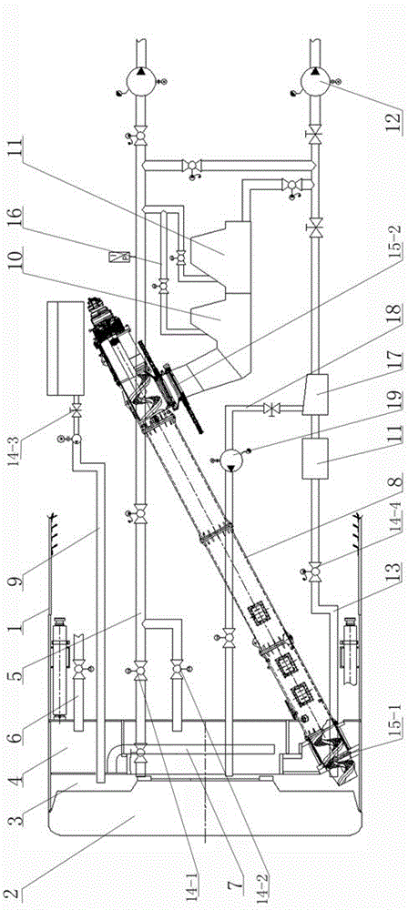
[0018] see figure 1 , a dual-mode shield machine, comprising a shield machine 1, a cutter head 2 is arranged at the front of the shield machine, an earth bin 3 is arranged behind the cutter head, and an air cushion bin is arranged behind the earth bin 3 4. There is a trailer behind the shield machine 1, the trailer is equipped with an earth pressure balance system and a mud-water balance system, the soil bin 3 and the air cushion bin 4 are connected with a slurry inlet pipe 5, and the air cushion bin The upper part of 4 is also connected with an air intake pipe 6, and a connecting pipe 7 is provided between the air cushion warehouse 4 and the soil warehouse 3; the earth pressure balance system includes a screw conveyor 8 extending into the soil warehouse 3, a The bentonite injection pipeline 9, the dilution box 10 at the rear o...


PUM


Abstract

The invention belongs to the field of shield construction, and discloses a double-mode shield tunneling machine. The double-mode shield tunneling machine comprises a shield tunneling main engine, a cutterhead arranged on the front portion of the shield tunneling main engine, an earth bin, an air cushion bin, an earth pressure balancing system and a slurry balancing system, wherein the earth bin, the air cushion bin are sequentially formed in the rear portion of the cutterhead. When the shield tunneling machine works, the shield tunneling machine can be switched between an earth pressure balancing tunneling mode and a slurry balancing tunneling mode according to the strata of practical tunnels, so that the shield tunneling machine is adaptive to tunneling under different geological conditions, and the adaptability to complex strata and the shield construction efficiency are improved. Meanwhile, a dilution tank and a breaker are mounted on the tail of a spiral conveyer to break large rocks to the grain size which can be conveyed by a slurry pump, and the broken large rocks are then discharged through a slurry pipeline, and in this way, the situation that large rocks cannot be discharged smoothly in a slurry mode can be prevented effectively.

Description

technical field [0001] The invention belongs to the field of shield tunneling, and in particular relates to a dual-mode shield tunneling machine. Background technique [0002] Common shield machines are divided into earth pressure balance shields and mud-water balance shields. The basic principle of the earth pressure balance shield is that the cutter head cuts the soil layer, and the cut soil enters the soil bin. When the soil in the soil bin is balanced with the pressure of the excavation surface, the slag is discharged by the screw conveyor in the soil bin. The slag discharge device at the slag outlet performs continuous slag discharge when the amount of slag discharge and the amount of propulsion are balanced; the basic principle of the mud-water balance shield is to set a partition at the rear of the shield cutter head, and A mud water tank (mud water pressure chamber) is formed between them, and the pressurized mud is sent into the mud water tank. Through the pres...

Claims


Application Information

Patent Timeline
IPC IPC(8): E21D9/06E21D9/08
Inventor 王杜娟贺开伟叶超张国良张志国赵新合苏志学赵万里李建斌谭顺辉郑康泰卓兴建杨爱军
Owner CHINA RAILWAY ENGINEERING EQUIPMENT GROUP CO LTD
Learn More