Connecting member for mounting of spring supports and hangers and manufacturing method of connecting member

A support and hanger and installation technology, which is applied in the direction of pipe supports, pipes/pipe joints/fittings, mechanical equipment, etc., can solve the problems of easy corrosion, aging, short service life, inconvenient maintenance and other problems at the interface, and achieve high temperature Anti-oxidation performance, avoiding the internal loosening of the tissue, and reducing the effect of grinding workload

Active Publication Date: 2015-09-02
BEIDELI ENERGY EQUIP JIANGSU CO LTD
View PDF7 Cites 8 Cited by
  • Summary
  • Abstract
  • Description
  • Claims
  • Application Information

AI Technical Summary

Problems solved by technology

[0002] Spring supports and hangers are mainly used for steam and water pipelines or boiler equipment in power plants, thermal displacement and equipment installations during operation. In the installation of supports and hangers, each part needs to be fixedly connected. In the past, positioning welding was used to The parts in the support and hanger are fixedly connected, but although this method is very strong, it cannot be disassembled at all, and it is inconvenient to maintain. The welded interface is easy to corrode and age, the service life is short, the cost is high, and the safety during welding is poor. A waste of resources; the welding method is abandoned in the prior art, and special connectors are used to effectively connect and fix the supports and hangers. At the same time, the long-term work safety of this connection method mainly depends on the working conditions of the contact surface and stress
[0003] At present, the connectors used in the installation of supports and hangers are particularly easy to corrode, easy to wear, and have insufficient strength due to working in an exposed environment for a long time. Therefore, it is necessary to develop a method that can overcome the above technical defects. The spring hanger connector has become a technical problem to be solved urgently by those skilled in the art

Method used


Image

  • Connecting member for mounting of spring supports and hangers and manufacturing method of connecting member

Examples


Embodiment 1

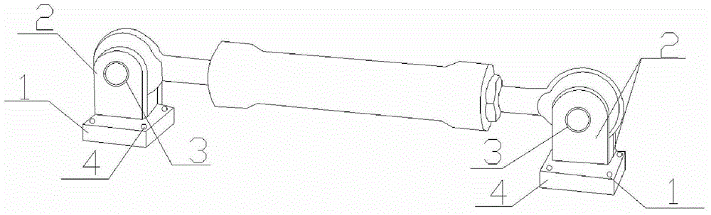
[0038] This embodiment provides a spring hanger installation connector, the structure is as follows figure 1 As shown, it includes a base 1 and a support frame 2, the support frame 2 is symmetrically arranged on the base 1, the support frame 2 and the base 1 form a U-shaped groove, and the support frame 2 is provided with a threaded hole 3, and the base 1 It is a cuboid structure, the four corners of the base 1 are provided with fixing holes 4, and the surface of the support frame 2 is coated with a zinc layer, wherein:

[0039] The base 1 and the support frame 2 are made of the same material, and the material for making the base 1 and the support frame 2 includes the following components in terms of mass percentage:

[0040]Cr: 1%, Mo: 0.8%, C: 0.04%, Co: 0.02%, Mn: 0.8%, P: 0.030%, S: 0.03%, Ni: 0.6%, Ti: 0.04%, W: 0.2%, V: 0.08%, Cu: 0.4%, Si: 0.8%, Nb: 0.05%, Ta: 0.02%, N: 0.02%, Mg: 0.03%, rare earth elements: 0.15%, and the rest are Fe and unavoidable impurities;

[00...

Embodiment 2

[0054] This embodiment provides a spring hanger installation connector, the structure is as follows figure 1 As shown, it includes a base 1 and a support frame 2, the support frame 2 is symmetrically arranged on the base 1, the support frame 2 and the base 1 form a U-shaped groove, and the support frame 2 is provided with a threaded hole 3, and the base 1 It is a cuboid structure, the four corners of the base 1 are provided with fixing holes 4, and the surface of the support frame 2 is coated with a zinc layer, wherein:

[0055] The base 1 and the support frame 2 are made of the same material, and the material for making the base 1 and the support frame 2 includes the following components in terms of mass percentage:

[0056] Cr: 2%, Mo: 0.9%, C: 0.02%, Co: 0.04%, Mn: 0.5%, P: 0.028%, S: 0.01%, Ni: 0.5%, Ti: 0.03%, W: 0.3%, V: 0.06%, Cu: 0.3%, Si: 0.5%, Nb: 0.03%, Ta: 0.04%, N: 0.01%, Mg: 0.04%, rare earth elements: 0.18%, and the rest are Fe and unavoidable impurities;

[0...

Embodiment 3

[0070] This embodiment provides a spring hanger installation connector, the structure is as follows figure 1 As shown, it includes a base 1 and a support frame 2, the support frame 2 is symmetrically arranged on the base 1, the support frame 2 and the base 1 form a U-shaped groove, and the support frame 2 is provided with a threaded hole 3, and the base 1 It is a cuboid structure, the four corners of the base 1 are provided with fixing holes 4, and the surface of the support frame 2 is coated with a zinc layer, wherein:

[0071] The base 1 and the support frame 2 are made of the same material, and the material for making the base 1 and the support frame 2 includes the following components in terms of mass percentage:

[0072] Cr: 3%, Mo: 1.0%, C: 0.03%, Co: 0.05%, Mn: 0.6%, P: 0.025%, S: 0.02%, Ni: 0.55%, Ti: 0.05%, W: 0.4%, V: 0.05%, Cu: 0.2%, Si: 0.2%, Nb: 0.04%, Ta: 0.06%, N: 0.015%, Mg: 0.02%, rare earth elements: 0.17%, and the rest are Fe and unavoidable impurities;

...


PUM


Abstract

The invention discloses a connecting member for mounting of spring supports and hangers. The connecting member comprises a base and supporting frames, the supporting frames are symmetrically arranged on the base, the supporting frames and the base form a U-shaped groove, a threaded hole is formed in each supporting frame, the base is of a cuboid structure, a fixing hole is formed in each of four corners of the base, a zinc layer is plated on the surface of each supporting frame, the base and the supporting frames are made by a same material, and the material is composed of Cr, Mo, C, Co, Mn, P, S, Ni, Ti, W, V, Cu, Si, Nb, Ta, N, Mg, rare earth element and the rest Fe and unavoidable impurities. The invention further discloses a manufacturing method of the connecting member. The manufacturing method is simple and easy to implement, pollution-free in manufacturing process and low in manufacturing cost, and the connecting member manufactured by the method is resistant to corrosion and wear, high in strength and tenacity and long in service life.

Description

technical field [0001] The invention relates to a connecting piece, in particular to a connecting piece used in the installation of a spring hanger and a preparation method thereof. Background technique [0002] Spring supports and hangers are mainly used for steam and water pipelines or boiler equipment in power plants, thermal displacement and equipment installations during operation. In the installation of supports and hangers, each part needs to be fixedly connected. In the past, positioning welding was used to The parts in the support and hanger are fixedly connected, but although this method is very strong, it cannot be disassembled at all, and it is inconvenient for maintenance. Waste of resources; the welding method is abandoned in the prior art, and special connectors are used to effectively connect and fix the supports and hangers. At the same time, the long-term work safety of this connection method mainly depends on the working conditions of the contact surface ...

Claims


Application Information

Patent Timeline
Patent Type & Authority Applications(China)
IPC IPC(8): F16L3/133B22C9/22C22C38/50
CPCB22C9/22C22C38/50F16L3/133
Inventor 郭芬阳伏程刘治联
Owner BEIDELI ENERGY EQUIP JIANGSU CO LTD
Why Eureka
Try Eureka