
Method for reducing number of cables through interconversion between parallel bus and serial bus

A mutual conversion and bus technology, applied in the direction of electrical digital data processing, instruments, etc., can solve the problems that the FPC line is difficult to pass through the rotating parts, it is difficult to accurately detect the assembly in place, and the number of cables is large, so as to reduce the number and performance requirements , The effect of high circuit integration

Active Publication Date: 2015-09-02
杭州紫来测控技术有限公司
View PDF5 Cites 15 Cited by
  • Summary
  • Abstract
  • Description
  • Claims
  • Application Information

AI Technical Summary

Problems solved by technology

Some portable devices have many key switches and knob operation keys, or are divided into multiple circuit printed boards due to structural limitations, and the signals of each printed board are connected by multiple cables, resulting in a large number of cables inside the device
For components with rotating functions, such as rotatable LCD displays, the use of FPC wires will bring the disadvantages of not being easy to pass through the rotating parts and easily damaged by multiple rotations
It is difficult to accurately detect whether the FPC cable is assembled in place during production and assembly. When it is subjected to multiple vibrations during transportation and use, poor contact is more likely to occur once the assembly is not in place.
Experienced engineers know that there are two main difficulties in EMC design of electronic equipment: one is the protection of each external port of the equipment; the other is the EMI design of each cable inside the equipment, too many internal cables bring great challenges to EMC design

Method used


Image

  • Method for reducing number of cables through interconversion between parallel bus and serial bus
  • Method for reducing number of cables through interconversion between parallel bus and serial bus
  • Method for reducing number of cables through interconversion between parallel bus and serial bus

Examples


Embodiment 1

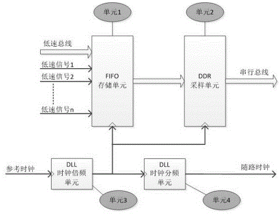
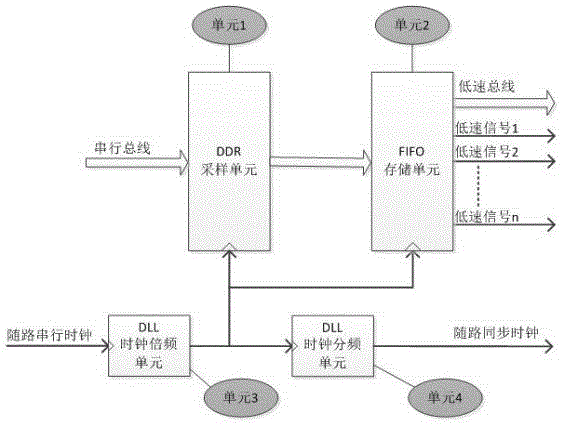
[0021] This embodiment describes a method for reducing the number of cables by converting between serial and parallel buses, using hardware description language to realize serial-to-parallel, parallel-to-serial functions, and DLL (digital phase-locked loop) frequency multiplication and DDR (Double Edge Sampling) function, and burn the compiled program into a small package CPLD or FPGA.

[0022] The present invention adopts a programmable logic chip of CPLD or FPGA, and requires DLL and DDR functions inside the chip. The pin rate and system clock rate of the chip should be at least twice that of all low-speed signals (need to satisfy the Nyquist sampling theorem).

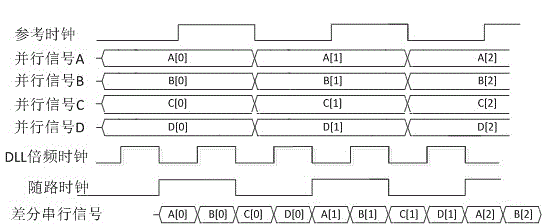
[0023] For the implementation method of parallel to serial function, please refer to figure 1 . figure 1 Various low-speed bus signals on the left and various low-speed signals are sent to the programmable logic chip, and the synchronous clock or other clocks of the low-speed bus are also sent to the programmable ...


PUM


Abstract

The invention designs a method for reducing the number of cables through interconversion between a parallel bus and a serial bus. A CPLD or FPGA programmable logic chip is adopted, and the CPLD or FPGA programmable logic chip has a delay-locked loop (DLL) function and a double data rate (DDR) function, the base pin rate if the chip and the frequency of a system clock are at least more than two times of frequencies all the low speed signals. Various low speed bus signals and various low speed signals are sent into the programmable logic chip, channel associated synchronized clocks or other clocks are sent into the programmable logic chip, too. An FIFO memory cell is used for caching data during serial-to-parallel convention. A DDR sampling unit is used for synchronously sampling when the low speed signals are in the rising edge and the falling edge of clocks, so that the frequency of the system clock in the programmable logic chip can be reduced by two times, so requirement of the frequency of the system clock in the chip can be reduced.

Description

technical field [0001] The invention belongs to the technical field of electronic circuits, and is mainly applied to portable electronic products that require high volume and assembly reliability, and relates to a method of realizing serial-to-parallel bus conversion through programmable logic language, thereby reducing the number of cables between circuit modules method. Background technique [0002] For some portable products with video display or video capture system, there are often high-speed parallel buses inside the circuit, such as RGB and BT.1120 buses in video, and FPC (Flexible Printed Circuit board) flexible Board or ordinary wire connection, the number of cables required is more, usually more than 30. Some portable devices have many key switches and knob operation keys, or are divided into multiple circuit printed boards due to structural limitations. The signals of each printed board are connected by multiple cables, resulting in a large number of cables insid...

Claims


Application Information

Patent Timeline
Patent Type & Authority Applications(China)
IPC IPC(8): G06F13/42
CPCG06F13/42
Inventor 闫树军李毅陈平山
Owner 杭州紫来测控技术有限公司
Learn More