Single sliding block rolling spray mode variable centroid aircraft model and designing method for structural layout parameters thereof
An aircraft and centroid-changing technology, which is applied in instruments, calculations, electrical and digital data processing, etc., and can solve problems such as complex slider layout and ablation of aerodynamic rudders.
- Summary
- Abstract
- Description
- Claims
- Application Information
AI Technical Summary
Problems solved by technology
Method used
Image
Examples
specific Embodiment approach 1
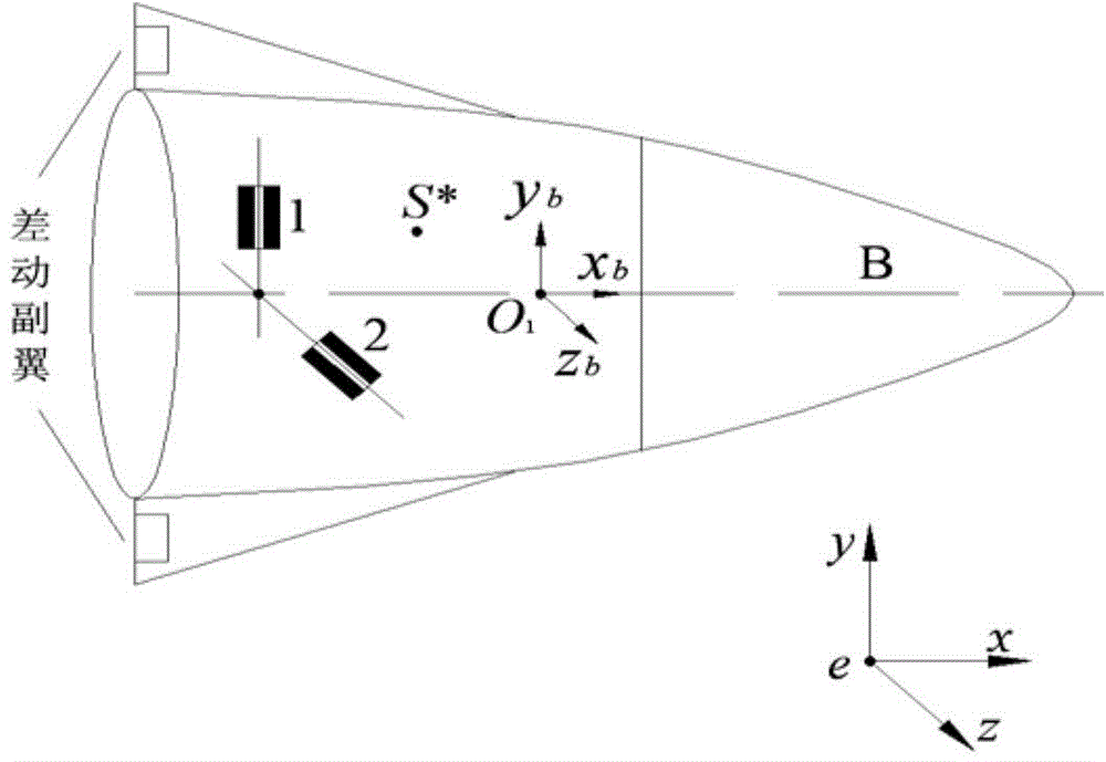
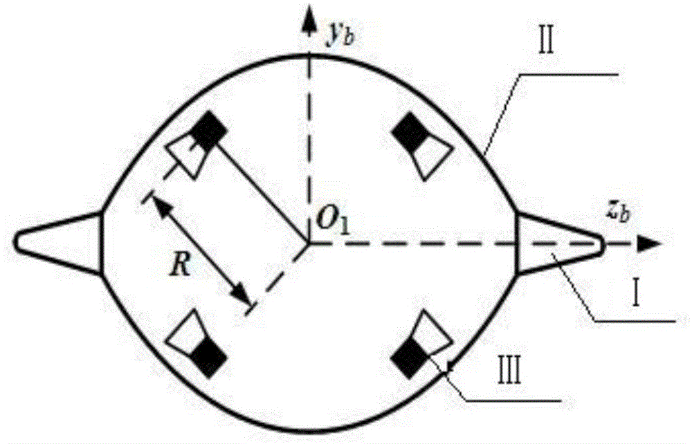
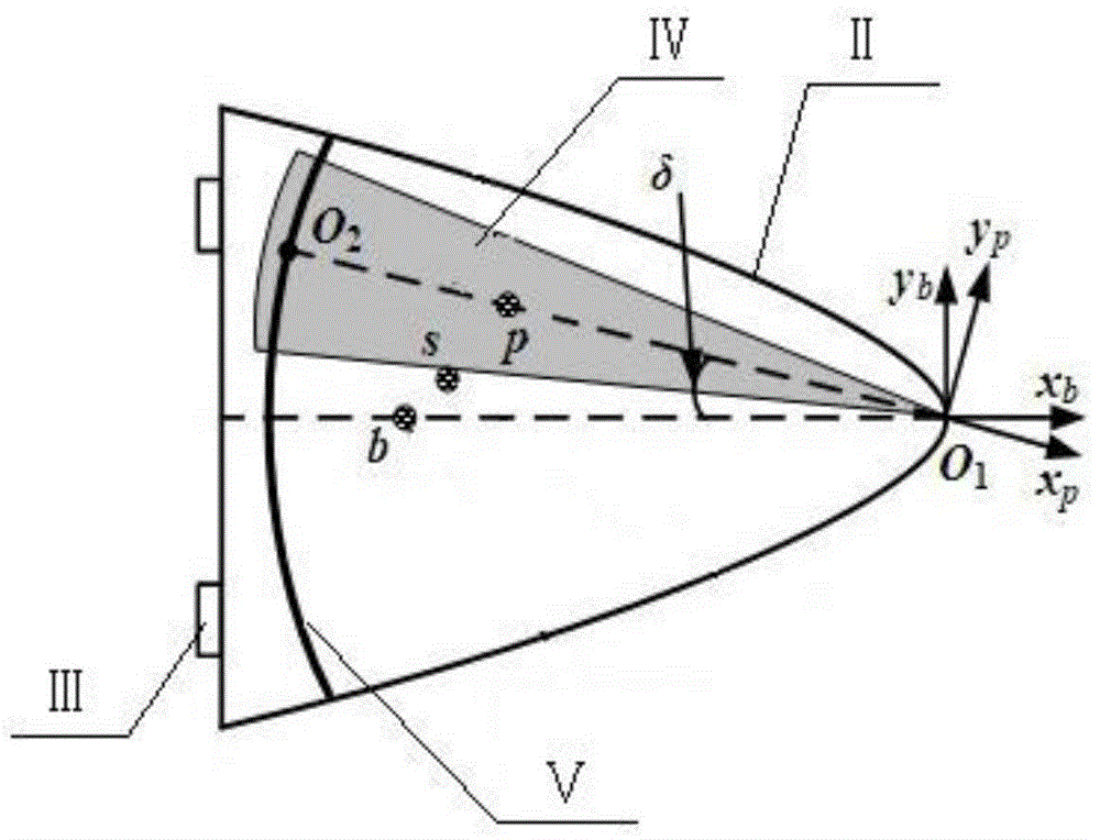
[0037] Specific embodiment one, in conjunction with Fig. 2 image 3 Illustrate this embodiment, the single-slider roll-spray mode variable center of mass aircraft model includes two fixed wings I, missile body II and roll-jet engine III, and the two fixed wings I are symmetrically arranged on both sides of the missile body II; it also includes The movable body IV inside the missile body II; the movable body IV is a cone, and the tip of the cone of the movable body IV and the head of the missile body II pass through the movable connection point O 1Connection; the tail of the missile body II is provided with a guide rail V, and the root of the cone of the movable body IV is connected to the O of the guide rail V at the tail of the missile body II. 2 point sliding connection; where O on rail Ⅴ 2 Under the action of the servo force, the point circles O along the guide rail V fixedly connected with the missile body 1 Do relative motion. By changing the relative position of movab...
specific Embodiment approach 2
[0038] Specific embodiment two, a kind of design method of the structural layout parameter of the single-slider rolling jet mode variable center of mass aircraft model for the single slider rolling jet mode variable center of mass aircraft comprises the following steps:
[0039] Step 1: Design the dynamic model of the aircraft:
[0040] Let the center of mass of the aircraft be s, the center of mass of the projectile body II be b, and the center of mass of the movable body IV be p; the above-mentioned systems all refer to the aircraft with variable center of mass; the degrees of freedom of the system include three-dimensional translation and three-dimensional rotation of the variable center of mass aircraft, and The two-dimensional rotation of the movable body IV; the whole system is regarded as a multi-rigid body system composed of the projectile II and the movable body IV, O 1 , O 2 is the connection point of the two components; the dynamic model is established using the mo...
specific Embodiment approach 3
[0051] Specific embodiment three: the design process of the dynamic model of step one aircraft in the present embodiment is as follows:
[0052] Step 1.1, define the coordinate system and parameters
[0053] In order to describe the dynamic model of the variable center of mass aircraft, three coordinate systems are defined, namely the inertial coordinate system, the projectile coordinate system and the movable body fixed coordinate system, where the origin of the projectile coordinate system is at the warhead O 1 Office, O 1 x b The axis is along the longitudinal axis of projectile II, pointing to the head is positive, O 1 the y b axis perpendicular to O 1 x b axis and parallel to the longitudinal axis of guide rail V, O 1 z b axis and the other two axes form a right-handed coordinate system; the origin of the fixed coordinate system of the movable body is also at the warhead O 1 , O 1 x p The axis is along the longitudinal axis of the movable body IV, O 1 the y p ...
PUM
 Abstract
Description
Claims
Application Information
 - R&D
- Intellectual Property
- Life Sciences
- Materials
- Tech Scout
- Unparalleled Data Quality
- Higher Quality Content
- 60% Fewer Hallucinations
Browse by: Latest US Patents, China's latest patents, Technical Efficacy Thesaurus, Application Domain, Technology Topic, Popular Technical Reports.
© 2025 PatSnap. All rights reserved.Legal|Privacy policy|Modern Slavery Act Transparency Statement|Sitemap|About US| Contact US: help@patsnap.com


