Ka-band parabolic antenna heat treatment method

A parabolic antenna, heat treatment method technology, used in heat treatment furnaces, heat treatment equipment, antennas and other directions, can solve the problems of poor rigidity, large deformation, reduced rigidity, etc., to improve rigidity, reduce thermal expansion and contraction coefficient, and meet the precision Effect

Active Publication Date: 2015-09-02
深圳市华讯方舟光电技术有限公司 +1
View PDF3 Cites 0 Cited by
  • Summary
  • Abstract
  • Description
  • Claims
  • Application Information

AI Technical Summary

Problems solved by technology

However, the rigidity of the steel plate becomes worse after being deformed by force, because when the steel plate is bent and stretched under force, the molecules are squeezed to generate heat, and the heat generated makes the rigidity of the original steel plate worse; Steel plate, after stamping deformation, its rigidity is also greatly reduced, and its deformation becomes large due to the influence of temperature and external force

Method used


Image

  • Ka-band parabolic antenna heat treatment method

Examples


Embodiment 1

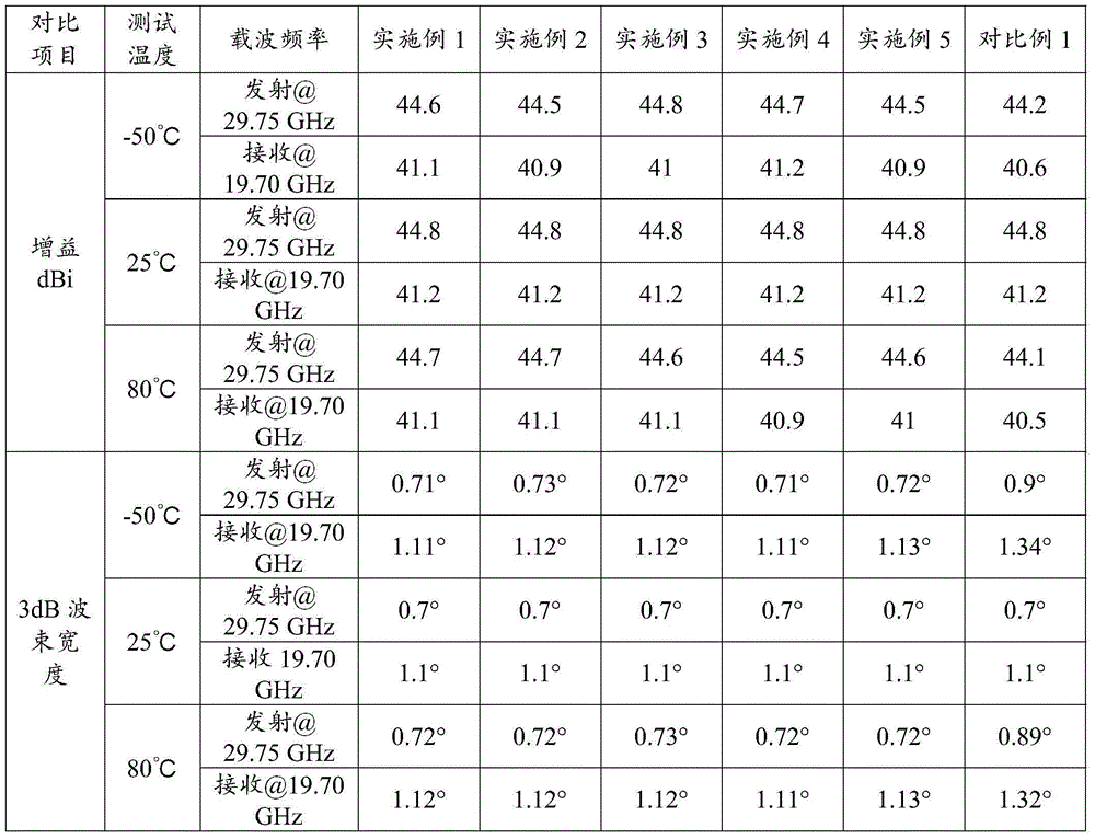
[0025] The steel plate is formed into a parabolic steel plate in a mold. Then the mold equipped with the parabolic steel plate was heat-treated in brine with a mass concentration of 20% and a temperature of 20° C. for 3 minutes. Finally, the mold after heat treatment is opened in 2.4×10 5 Clamp the mold and press the parabolic steel plate under the pressure of 7s. The performance of the parabolic antenna finally obtained is shown in Table 1.

Embodiment 2

[0027] The steel plate is formed into a parabolic steel plate in a mold. Then the mold equipped with the parabolic steel plate was heat-treated in brine with a mass concentration of 25% and a temperature of 10° C. for 3 minutes. Finally, the heat-treated mold is opened at 2.5×10 5 Clamp the mold and press the parabolic steel plate under the pressure of 5s. The performance of the parabolic antenna finally obtained is shown in Table 1.

Embodiment 3

[0029] The steel plate is formed into a parabolic steel plate in a mold. Then the mold equipped with the parabolic steel plate was heat-treated in brine with a mass concentration of 22% and a temperature of 15° C. for 2.5 minutes. Finally, the heat-treated mold is opened at 2.43×10 5 Clamp the parabolic steel plate under the pressure of 8s. The performance of the parabolic antenna finally obtained is shown in Table 1.


PUM


Abstract

The invention discloses a Ka-band parabolic antenna heat treatment method. The method comprises a step of moulding a steel plate into a parabolic steel plate with a die; a step of placing the die with the parabolic steel plate in salt water for heat treatment; and a step of opening the die subjected to the heat treatment and locking the die for laminating the parabolic steel plate. The method provided by the invention is good; and when the bad weather changes, the thermal expansion coefficient of the antenna steel material becomes extremely small, so that the design directionality, the high focusing radiation and the low interference of the antenna are ensured.

Description

technical field [0001] The invention belongs to the technical field of parabolic antenna manufacturing, and in particular relates to a heat treatment method for a Ka-band parabolic antenna. Background technique [0002] The antenna system is the front-end equipment of radar, satellite communication, radio astronomy and other multi-purpose electronic equipment. High-precision antenna is the key equipment of the antenna system, especially for high-frequency antennas such as Ka-band. The accuracy of the antenna reflector is related to the operating frequency, and it is generally required that the maximum value of the Ka-band antenna reflector accuracy δ should be less than λ / 32. (Taking 30GHz as an example, 10 / 32=0.3125mm) is far higher than the Ku-band and C-band requirements. It is necessary to consider these factors in the selection of antenna reflector material. The reflective surface must be made of corrosion-resistant materials. Materials such as iron, stainless steel,...

Claims


Application Information

Patent Timeline
Patent Type & Authority Applications(China)
IPC IPC(8): H01Q15/16C21D8/00C21D9/00
Inventor 吴光胜边天明丁庆
Owner 深圳市华讯方舟光电技术有限公司
Why Eureka
Try Eureka